EI-1000 & 2000: Setup, Calibration and Troubleshooting.
Page 4 of 19
EI-1000 and EI-2000: Installation and wiring.
1. Chose a mounting location for the scale base and instrument. WT3600,
ECS150x, LP4310, and any scale that has a hinge at one end must be
bolted down before use. The DCS-302, EDS-400, C3600, C7200 and DS-
750 should be bolted down for best results.
2. Mount instrument and scale base. See the instrument and scale manuals
for drawings if needed.
3. Wire scale base. Use TB4 on EI1000 units. See Scale Wiring section for
details. The EI-1000 has a shorting jumper on TB5 (+S,-S,-E). Do not
remove this jumper.
4. Check S2 and set for the proper power input voltage 230 or 115 V.A.C. S2
is directly above the power terminal TB1.
5. Wire up A.C. Power on TB1. G is earth ground. N is Neutral or L2. H is
Hot or L1.
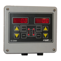
6. Wire 4-20 outputs, if needed, on TB3. CH1 is the left display. CH2 is the
right display. The EI-1000 uses CH1.
7. Power up unit. The instrument should show a weight reading if everything
is wired properly. If the instrument shows A-OL, double check the scale
wiring. See the alternate color codes table below for the 4 possible color
codes.
8. When the scale is showing a weight reading, push down on the deck or
disk. The gross weight should go positive. If the reading goes negative,
reverse wires on the +S and –S terminals and recheck.
9. Calibrate the system. See the next page.
10. Setup and calibrate the 4-20 mA outputs if needed.