Assembly and Operation Instructions
2600A-Plus_MAR2024 PAGE 5
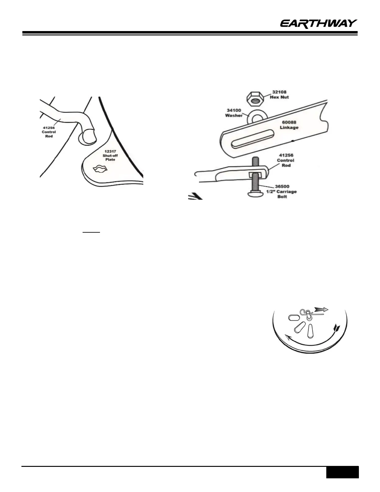
STEP 13: Take the bent end of the Control Rod and place it into the keyed shut off plate under the hopper making sure
to take out the bow tie clip. The Control Rod will be placed into the first notch closest to the end of the plate. Once the
Control Rod has been placed through the notch secure the placement by replacing the bow tie clip.
TIP: Make sure that the Control Rod is above the Lower Handles. There will be two holes in your Shutoff Plate, the
Control Rod will go in the hole closest to the edge as shown below.
STEP 14: Install the ½” carriage bolt through the Control Rod and install the SM flat washer and hax nut on the carriage
bolt as shown above. NOTE: This connection will be loose to allow for the necessary calibration and proper performance
of the spreader.
STEP 15: CALIBRATION: THIS STEP ENSURES THAT YOUR SPREADER IS PROPERLY ADJUSTED TO GIVE YOU A CORRECT
STARTING POINT TO APPLY MATERIALS AT THE CORRECT SETTING. Pull the Control Lever back to #30 on the Gauge and
Lever Assembly, then push the shut-off plate forward until the shut-off and the drop holes are fully open. Now tighten
the Hex Nut on the ½” Carriage Bolt on the Linkage Assembly (parts from Step 14). Check to confirm calibration by
closing the Control Lever to #0, then reopening to #30. If all drop holes are fully closed at #0 and open at #30 then your
unit has been calibrated correctly.
STEP 16: Take your Agitator Pin and insert it into the portion of the Pinion Shaft that is
located inside the Hopper.