Assembly and Operation Instructions
2600A-Plus_MAR2024 PAGE 4
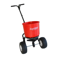
STEP 10: Place the Handle Shaft between the two Lower Handles and secure using the bolts and nuts selected in Step
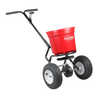
STEP 11: Take Gauge and Linkage Assembly and line up the holes with the Handle Shaft and Upper Handles. Insert (2)
¼”-20 X 1/ ½ bolts through the Gauge and Linkage Assembly, Upper Handles, and Handle Shaft. Secure with (2) 1/4”-20
nylon lock nuts. NOTE: Make sure the Gauge and Linkage Assembly is placed on the left side of the Handle. The
numbers, wing nut, and lever will be facing out.
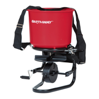
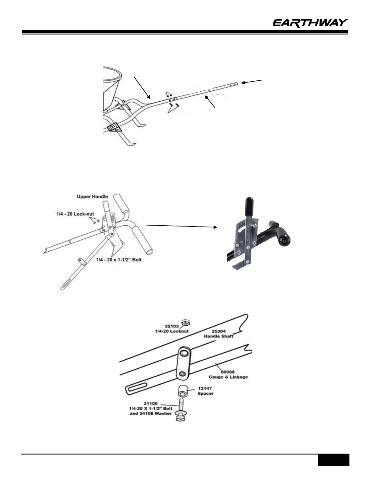
STEP 12: Attach Linkage Pivot with a ¼”-20 X 1 ½” bolt, MD flat washer, black spacer, and lock nut (shown below).
¼-20 Lock Nuts