For more information visit: www.eaton.com IB01602008E
Instructional Booklet
Page 10 Effective: March 2014
ATC-300 Breaker Based Transfer Switch
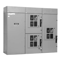
Figure 11.Typical (225-1200 A) Vertical Design Transfer Switch Equipment (Door Open and Deadfront Cover Removed).
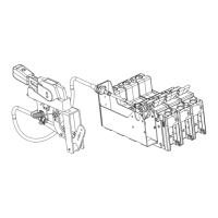
3.2.3 Transfer Mechanism (225-1200 A)
The transfer mechanism transfers between power sources
through a motor-driven, ratchet-type operation. A rotational
motion is created on an indicator wheel by the ratchet’s opera-
tion. The indicator wheel is attached to rigid shafts that convert
the rotary motion into vertical linear motion. Opening and closing
the switching devices is accomplished as a result of this vertical
linear motion. The transfer mechanism is mounted in front of the
molded case switches (Figure 6).
NORMAL POWER
SOURCE MOLDED
CASE SWITCH
GROUND
CONNECTIONS
MANUAL
OPERATING
HANDLE
INDICATOR
WHEEL
TRANSFER
MECHANISM
MOTOR BRAKE
BOARD
EMERGENCY
POWER SOURCE
MOLDED CASE
SWITCH
NEUTRAL
CONNECTIONS
LOAD LUGS (TOP ENTRY)
POWER PANEL

 Loading...
