For more information visit: www.eaton.com IB01602008E
Instructional Booklet
Page 38 Effective: March 2014
ATC-300 Breaker Based Transfer Switch
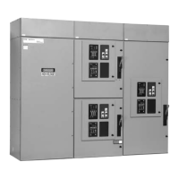
Figure 39.Horizontal Power Panel
Step 3: Turn the generator OFF at the generator control panel.
This will prevent unexpected activation of the generator.
Step 4: Connect the Engine Generator Start wires to terminals 13
and 14 on the J-5 connector on the ATC-300 Controller
(Figure 40). This contact is CLOSED whenever the
engine generator is needed, and should be connected to a
generator controller. NEVER connect directly to a starter
solenoid or ignition system. See the Genset manufacturer
instruction leaflet for recommended wire sizes and loca-
tion procedures.
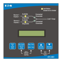
Step 5: Apply Utility (Source 1) power. If the switch is properly
applied for the system voltage ordered, the display should
work and the Source 1 Available white LED should light
(Figure 41). Using a voltmeter, check for proper system
voltage on Source 1 and load terminals. Check all phases
on a 3-phase switch. Voltage measurements should be
taken phase to phase and phase to neutral.

 Loading...
