Eaton.com/bussmannseries6
Instruction Sheet IS10207 Rev 3
Effective July 2015
BSPD SPDs for switchgear and power distribution panels
12.05
(306.1)
5.24
(133.1)
0.78
(19.8)
2.00
(50.8)
3.48
(88.4)
4.41
(112.0)
Ø0.20
(Ø5.1)
10.48
(266.2)
0.68
(17.3)
7.28
(184.9)
5.27
(133.9)
1.00
(25.4)
11.25
(285.8)
7.47
(189.7)
0.40
(10.2)
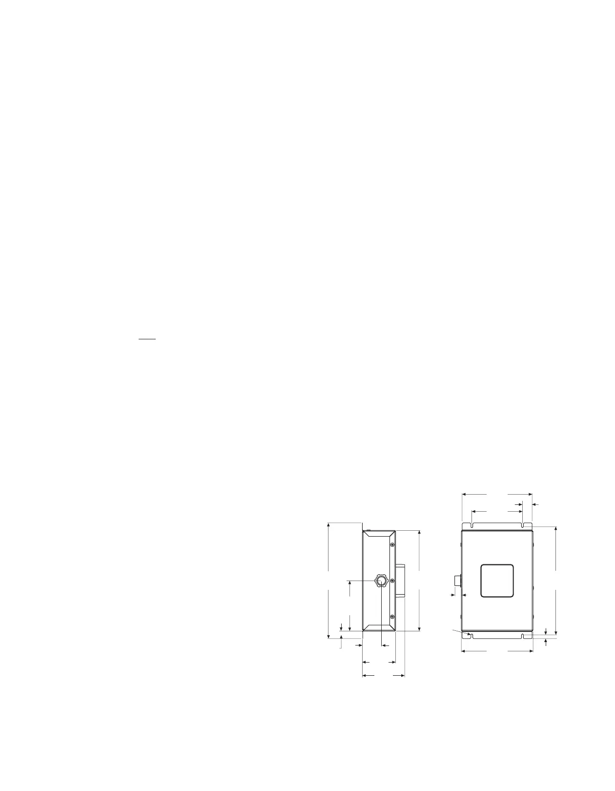
Figure 2. 120-200kA Units in a NEMA 1 Enclosure,
Weight = 6.8 lbs (3.1 kg)
2.0 Installation
Important: Read these instructions carefully to assure proper
installation. Ensure all fasteners and connections are tightened to
specified values. Installation in a manner inconsistent with these
instructions will void the warranty.
To ensure integrity of finished installation, do NOT install the SPD if
it has been dropped or abused during the installation process.
The SPD contains no user serviceable parts and cannot be repaired.
Performing the following may compromise the unit’s performance
and will void the warranty:
•
Do NOT open or tamper with NEMA 1 units
•
Do NOT remove deadfront of, or tamper with NEMA 4X units
•
Do NOT megger or hi-pot test the unit
•
Do NOT install in a system that has a nominal voltage greater
than the unit’s rated nominal system voltage
•
Do NOT install with lead lengths less than six (6) inches.
Doing so will void the warranty
2.1 Preparation for installation
Type 1 and Type 2 SPD NOTE: The
Basic
configuration BSPD
units are Type 1 SPDs that can be installed on either the lineside or
loadside of the service entrance panel overcurrent protective device.
The
Standard
and
Standard with Surge Counter
configurations
are Type 2 SPDs that can only be installed on the loadside of the
service entrance panel overcurrent protective device.
Before installing a BSPD unit, do the following:
•
Verify the SPD’s UL Type is correct for the intended installation —
see above note on Type 1 and Type 2 SPDs
•
Confirm that the system voltage and type (Wye/Delta) matches
the SPD you are installing. Check the label on the side of the SPD
for system voltage and type (see
Catalog Number System
on
page 11 for details).
•
Verify that the area is clear of any dirt, debris or clutter that may
hamper the installation process
•
Verify that there is enough space to install the SPD (see
dimensions in Section 2.3,
Installation Procedures
).
•
Confirm that all tools, equipment and supplies needed for the
installation are available
•
Check the facility grounding system. All grounding, bonding and
earthing must meet the NEC
®
and any other national, state and
local electrical codes and agency standards.
2.2 Installation locations
The BSPD SPD can be installed next to, above or below any existing
electrical cabinet or panelboard.
The ideal mounting location is as close to the electrical enclosure
and electrical connection points as possible. The BSPD unit should
be mounted in such a way as to minimize lead length and any sharp
bends in the wiring conduit.
2.3 Installation procedures
1. Before mounting the SPD, first determine the location and
ensure that the mounting surface can support the weight of the
SPD (See Figures 2 , 3 and 4 for model weights). For maximum
performance, mount the unit as close as possible to the wiring
connection points within the enclosure.
2. Lay out the four enclosure mounting holes using the enclosure
dimensions provided in Figures 2, 3 and 4. Drill the appropriate
holes per the product dimensions and use #10 fasteners for
NEMA 1 enclosures and 1/4” fasteners for NEMA 4X enclosures.
3. Determine the correct length and install metal conduit onto the
SPD. NEMA 1 SPDs have a 3/4 inch trade size chase nipple and
NEMA 4X SPDs have a 3/4 inch trade size hub. Route all Phase,
Neutral (where applicable), Ground and Form C contact wires
(where applicable) through the conduit.
4. Determine the hole location on the receiving electrical cabinet/
panelboard and either remove the knock-out provided or drill/
punch the appropriate size hole at this location. Route the SPD
wires through the enclosure hole and mount the SPD unit using
the appropriate fasteners for the enclosure’s NEMA rating. Be
sure to remove metallic shavings/plug created during the drilling
or punching process.
Note: On NEMA 4X enclosures, be sure to use appropriate
fittings/gaskets that retain the integrity of the SPD’s and
electrical cabinet’s NEMA 4X ratings after being installed per the
manufacturer’s specifications.
5. Select the correct wiring diagram for the SPD you are installing.
You must refer to this diagram while wiring the SPD. See Figures
6 and 7.
6. Determine the wire lengths required to make the Ground and
Neutral (where applicable) connections and cut the wires to
the appropriate lengths. Again, maximize SPD performance by
keeping these wires as short as possible.
7. Determine the wire lengths required to make the SPD Phase
connections and cut the wires to the appropriate length. (To
maximize SPD performance keep wire length as short as
possible.) Connect the Phase wires.
Note: For wire lengths longer than six (6) inches, maximize SPD
performance by twisting once for every four (4) inches of wire
length.
8. BSPD
Standard
and
Standard with Surge Counter
configurations
have a Form C contact relay for remote monitoring. The Form
C contacts are rated at 150Vac/125Vdc at 1A max. Make the
remote monitoring connections per the Form C contact relay
wire color codes in Figure 5. Follow all national, state and local
electrical codes and agency standards when making these
connections.

 Loading...


