Eaton.com/bussmannseries8
Instruction Sheet IS10207 Rev 3
Effective July 2015
BSPD SPDs for switchgear and power distribution panels
3.0 Operating features
3.1 General
The BSPD SPDs are available in three configurations:
•
Basic
•
Standard
•
Standard with surge counter
Each configuration is described below.
The BSPD SPDs require no operator involvement other than to
monitor the display panel to determine SPD status.
After installation and system power is applied, the SPD automatically
begins protecting downstream electrical equipment from voltage
transients.
Some SPD units have a Form C contact relay that allows for the
remote monitoring of SPD status. Form C contact relay wires are
permanently connected to the SPD.
3.2 Displays and indicators
All BSPD configurations have a system status display panel. The
display panel is slightly different for each.
All display panels have green and red Light Emitting Diodes (LEDs)
on each phase to indicate the protection status. Green indicates
the phase is protected. Red indicates a loss of protection. Units for
Wye electrical system have an additional set of green/red LEDs to
indicate Neutral-to-Ground protection status.
standard
and
standard with surge counter
units have an audible
alarm will sound when any red LED illuminates.
Specific operating conditions displayed for each configuration are
described below.
3.2.1 Basic
The
basic
configuration display panel is shown in Figure 7.
Figure 7. Basic configuration display
The
Basic
configuration is a Type 1 SPD that can be installed on the
lineside or loadside of the service entrance overcurrent protective
device and has the following features:
•
Green LEDs: Illumination indicates the phase is fully protected,
and operating normally. Note: An illuminated green LED on a
phase does NOT indicate power ON/OFF status, just the surge
protection status of that phase. On Wye units with a Neutral
wire, an additional illuminated green LED indicates the Neutral-to-
Ground is fully protected, and operating normally.
•
Red LEDs: Illumination indicates a loss of protection, and that one
or more protective devices are inactive and unavailable for that
phase. Note: Red LEDs do NOT indicate power ON/OFF status,
just the surge protection status of that phase. On Wye units with
a Neutral wire, an additional illuminated Red LED indicates loss of
Neutral-to-Ground protection.
3.2.2 Standard
The
Standard
configuration display panel is shown in Figure 8.
Figure 8. standard configuration display
The
standard
configuration is a Type 2 SPD that can only be installed
on the loadside of the service entrance overcurrent protective
device and has the following features:
•
All features of the
basic
configuration
•
One Form C contact relay rated at 150Vac/125Vdc @1A. max
•
Normal operating conditions; N.O. = OPEN, N.C. = CLOSED
•
Loss of protection on any phase or loss of power;
N.O. = CLOSED, N.C. = OPEN
•
Audible alarm with reset push button
•
EMI/RFI filtering up to 50dB from 10kHz to 100MHz
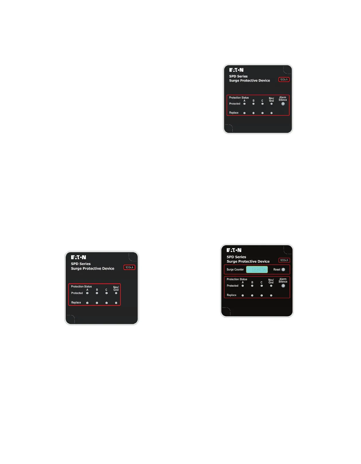
3.2.3 Standard with surge counter
The
standard with surge counter
configuration display panel is
shown in Figure 9.
Figure 9. standard with surge counter configuration display
The
standard with surge counter
configuration is a Type 2 SPD
that can only be installed on the loadside of the service entrance
overcurrent protective device and has the following features:
•
All features of the
standard
configuration
•
Surge counter with LCD screen
•
Counter reset push button to RESET the surge counter to zero

 Loading...


