19
Technical Data MN019001EN
Effective November 2015
Bussmann series
PV Combiner box
EATON www.eaton.com
Monitoring unit configurations
EcoMode
Activating the EcoMode (register 300 = 1) enables you to drasti-
cally reduce the type S1 string monitoring module power demand:
from approx. 0.9 W to only 0.2 W.
To do this the measurement section in the type S1 string monitoring
module is switched off completely after each measurement and
also the display illumination. Every minute the measurement section
is activated for a new measurement and then switched off again.
The module communication section (modbus interface) is however
always active, i.e. the measurements can be read out any time. New
measurements are however only produced once per minute.
Synchronization of modules (data acquisition modes)
A problem with larger solar power systems arises due to the
serial transmission of data and the limited transmission speed of
the modbus link: The values of each PV string are normally inter-
rogated individually and sequentially. Consequently a time offset
arises between the data of the first (t1) and the last PV string (tn),
which can be in the range of several seconds. The measurements
are therefore not acquired synchronously and cannot be directly
compared. (With the type S1 string monitoring modules all PV
strings are acquired simultaneously within a module.)
The type S1 string monitoring modules offer you the possibility of
preventing this time delay in that you send a special command
simultaneously to all modules (broadcast) to “freeze” the current
measurements of all PV strings of all modules simultaneously.
Then you can interrogate and transmit these values consecutively
from all type S1 string monitoring modules. Although the data
here arrive at the controller with a time offset, the values them-
selves have been acquired simultaneously and synchronously.
Time offset due to serial communication in standard PV systems
Synchronous aquisition of all measurements of all PV strings with
type S1 string monitoring modules
Procedure
1. Send a broadcast message by writing a value in register 302 (sync register)
via the modbus address 0 (broadcast address). Thus, in each module, the
actual measured values are written into the (internal) registers 60 to 101 and
the broadcast value is transferred to register 59.
2. Now read out sequentially from all modules the measured val ues of the
individual strings from registers 60 to 101 and the value of register 302 from
register 59.
Since the modules transfer the measured values of the individual
strings simultaneously into the sync registers 60 to 101, this method
delivers synchronously acquired measurements of all PV strings.
Using the response delay
Depending on the measurement mode for the current and voltage
measurements the response time for a query (request) through the
modbus interface is between 5 and 20 milliseconds. You can use
register 208 to extend the time up to the response if this is too
fast for the modbus master used and, therefore, there is a risk that
responses are not recognized, because they were already available
on the bus shortly after the request. Specify the addi tionally desired
delay in milliseconds in register 208 as a numeri cal value.
Optional external connection port
Your Eaton’s Bussmann series combiner box is maybe fitted with
an external 9 pin male D-Sub connection port, to interrogate
modbus A and B commands at your convenience without opening
the enclosure. This connector is IP65 rated, achieved using a seal
around the inside edge of the connector. When the connector is
not in use, the IP65 rated cover must be replaced on the socket to
both protect it and maintain the ingress rating.
Optional external connection port
The pins of the connector are mapped as below –
Pin configuration for optional external connection port
Optional wireless communications
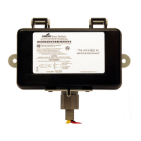
Your Eaton’s Bussmann series combiner box may be fitted with
either a Eaton’s Bussmann series industrial wireless or zigbee
wireless communications unit, enabling remote connection to
the combiner box without the need for additional communication
wiring. Please refer to the specific wireless instruction manuals
relevant to the type of wireless unit installed in your combiner
box.
 Loading...
