I.L. 17403
Page 12
Effective 9/04
provided one side of the DC voltage source is grounded
to the same reference point as terminal C.
CONTROL CIRCUIT CHECK
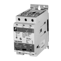
Since an Advantage motor controller can be controlled
with an AC signal of 24 to 120 volts at terminals 3 and P,
a high impedance fault in the control circuit that bypasses
the STOP or START pushbuttons so as to supply voltage
in this range can cause controller malfunction, i.e., the
fault causes the controller to turn on or the fault nullifies
the STOP button. Check pushbutton stations for liquid
buildup and the leads to 3 and P for voltage when none
should be present.
CONTROL POWER AND TERMINALS, Contd
Control power terminals for the motor controller are shown
in Figure 3. All the terminals must be supplied by the
same phase. The preferred source is a control power
transformer whose primary windings are connected across
phase L1-L2, although phases L2-L3, phase L3-L1, or
phases A, B, and C will provide satisfactory performance.
See Figure 13. In any case, the power supplied to terminals
3 and P must be from the same phase as the power to
terminals E and C, except that a DC signal in the range
of 5 to 125 volts (24 to 96 volts for Model E or later) may
be supplied to terminals 3 and P for remote control,
TABLE IX - AUXILIARY CONTACT RATINGS
Voltage Make Break
NEMA A600
120-600VAC 7200VA 720VA
28 - 120VAC 60A 6A
NEMA Q300
28-300VDC 69VA 69VA
TABLE X - RENEWAL PARTS
Description Order
Replacement Contacts, Size 3* WCK33
Replacement Contacts, Size 4* WCK43
Replacement Coil, 110-120V 1A48101G01
Replacement Circuit Board See Table XI
DIP Switch Windows (10/pkg) WDIPSW10
* These kits include contacts, screws, and crossbar
assembly with armature attached
ACCESSORIES
Description Catalog Number
Internal Trip Indicator WLED
External (remote) Reset for W200, WRST24
24 inch Leads*
External (remote) Reset for W200, WRST72
72 inch Leads*
External (remote) Reset/Trip Indicator WRSTL24
for W200, 24 inch Leads*
External (remote) Reset/Trip Indicator WRSTL72
for W200, 72 inch Leads*
Control Circuit Terminal Block with WTBF16
2.0A fuse and 2 tie points to accept
solid, stranded, or lugged conductors
for W200 and W201
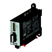
Communications Module - WPONI
Data, Status, and Control
Communications Module - DeviceNet WPONIDNA
Central Monitoring Unit WCMU
to receive WPONI output
Alarm Module with one NO Contact WBELL
Terminal Lug Kit - Size 3 and 4 WTX34
(one lug per kit)
Advantage Metering Module WMETER
Advantage Programming Module WAPM
* There is no trip indication available when this accessory
is used other than via a communications network.

 Loading...


