i-on30EX/EXD Installation
Page 17
LEDs are enabled. For
example:
3. Leave local programming
mode and save your
changes (see page 17).
To Change Backlight Settings
1. Enter Local Programming
mode (see above)
2. Press . The display shows
the current status of the
backlight LEDs, for
example:
3. Press repeatedly to select
one of the following:
Backlight timed ().
The backlight will glow for
12 seconds after the last
keypress. The action of
the backlight depends on
the programming of the
control unit (which must
have Release 3 software
or higher installed).
4. Leave local programming
mode and save your
changes (see below).
To Disable/Enable the Status OK LED
1. Enter Local Programming
mode.
2. Press repeatedly until
the display shows:
3. Press repeatedly to
select one of the
following:
Status OK LED OFF ().
The green status LED
under the navigation key
will glow for 20 seconds
after the last press (this
may be useful when the
keypad is placed in
bedrooms that should be
completely dark at night).
4. Leave local programming
mode and save your
changes.
To Disable/Enable the Status Fault
LED
1. Enter Local Programming
2. Press repeatedly until
the display shows:
3. Press repeatedly to
select one of the
following:
Status Fault LED OFF
().
The red Fault LED under
the navigation key is
disabled, and will not
glow for any fault reports.
4. Leave local programming
mode and save your
changes (see below).
To Leave Local Programming Mode
and Save Changes
EITHER:
Press
OR
Close the keypad tamper.
The keypad saves the changes you have made in
its local memory.
You can now remove 12Vdc power, if required, or
leave Installer Menu on the control unit.
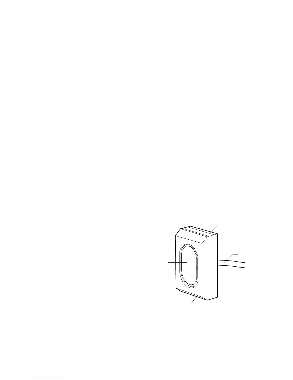
KEY-EP External Prox Reader
Figure 22 shows the outside details of the external
prox reader KEY-EP:
1. LED window.
2. Retaining Screw.
3. Removable Fixing Plate.
4. Permanently attached cable.
Figure
External Prox Reader KEY-EP
Siting the External Prox Reader

 Loading...


