i-on30EX/EXD Before You Begin
Page 9
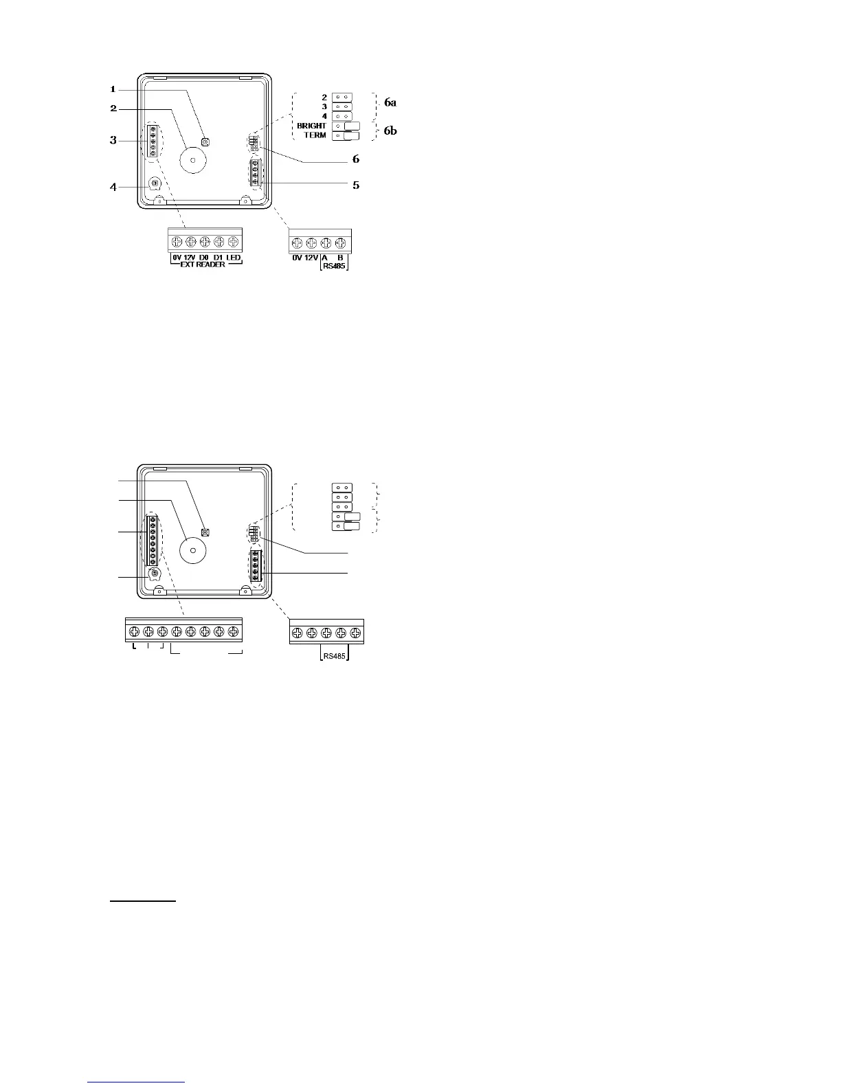
1. Tamper switch.
2. Sounder.
3. Connector for KEY-EP.
4. Sounder volume control.
5. Connector for control unit bus.
6. Jumpers for:
6a Addressing (not used in i-onEX
control units).
6b LED functions and RS485 bus
termination.
Figure
KEY-KP01 Keypad PCB
1. Tamper switch.
2. Sounder.
3. Connector for KEY-EP. Terminals for
zones
4. Sounder volume control
5. Connector for data bus and output
terminal.
6. Jumpers for addressing and LED function:
6a Addressing (not used in i-onEX
control units)
6b LED functions and RS485 bus
termination.
Figure
KEY-KPZ01 Keypad PCB
Expanders
To open any of the expander cases undo the
single screw, pull the top of the lid away from the
case and then lift out.
Figures 14, 16 and 15 show the interior of the
wired and radio expanders.
2
3
4
BRIGHT
TERM
0V 12V A B
0V 12V D0 D1 LED
EXT READER
Z1 Z2
OP
1
6a
6b
3
4
5
6
2

 Loading...


