Before You Begin i-on30EX/EXD
Page 10
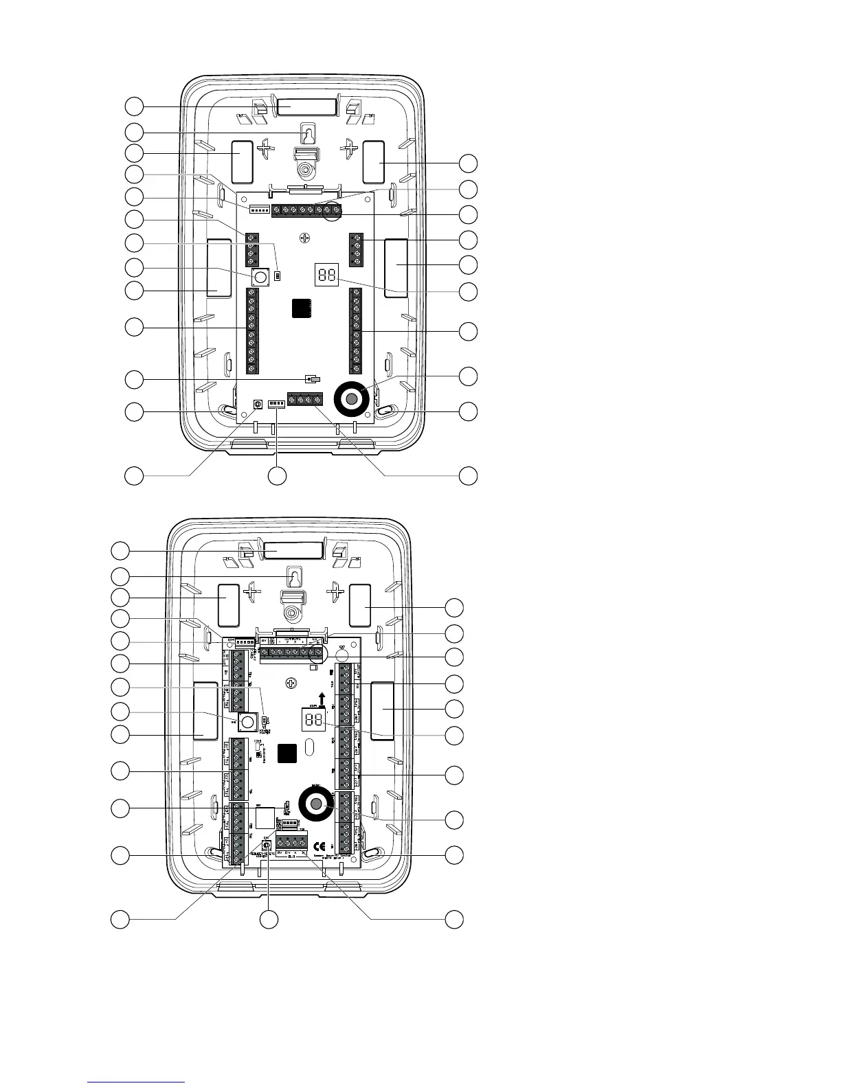
1. Cable entry (also behind PCB).
2. Central keyhole.
3. PCB.
4. Relay card (i-rc01) connector.
5. Aux power.
6. Link to enable/disable front/rear
tamper switch.
7. Lid tamper (rear tamper behind
pcb).
8. Zone connectors
9. Bus termination jumper.
10. Fixing holes.
11. Addressing button.
12. Engineering keypad connector
13. Bus cable connector.
14. Sounder.
15. Zone connectors.
16. Bus address display.
17. Aux power.
18. Loudspeaker connectors.
19. Outputs.
1. Cable entry (also behind PCB).
2. Central keyhole.
3. PCB.
4. Relay card (i-rc01) connector.
5. Aux power.
6. Link to enable/disable front/rear
tamper switch.
7. Lid tamper (rear tamper behind pcb).
8. Zone connectors
9. Bus termination jumper.
10. Fixing holes.
11. Engineering keypad connector.
12. Addressing button.
13. Bus cable connector.
14. Sounder.
15. Zone connectors.
16. Bus address display.
17. Aux power.
18. Loudspeaker connectors.
19. Outputs.
1
1
2
3
1
8
7
5
6
4
10
9
11 12 13
10
1
16
15
14
1
17
18
19
1
1
2
3
1
8
7
5
6
4
10
9
11 12 13
10
1
16
15
14
1
17
18
19

 Loading...


