i-on30EX/EXD Installation
Page 23
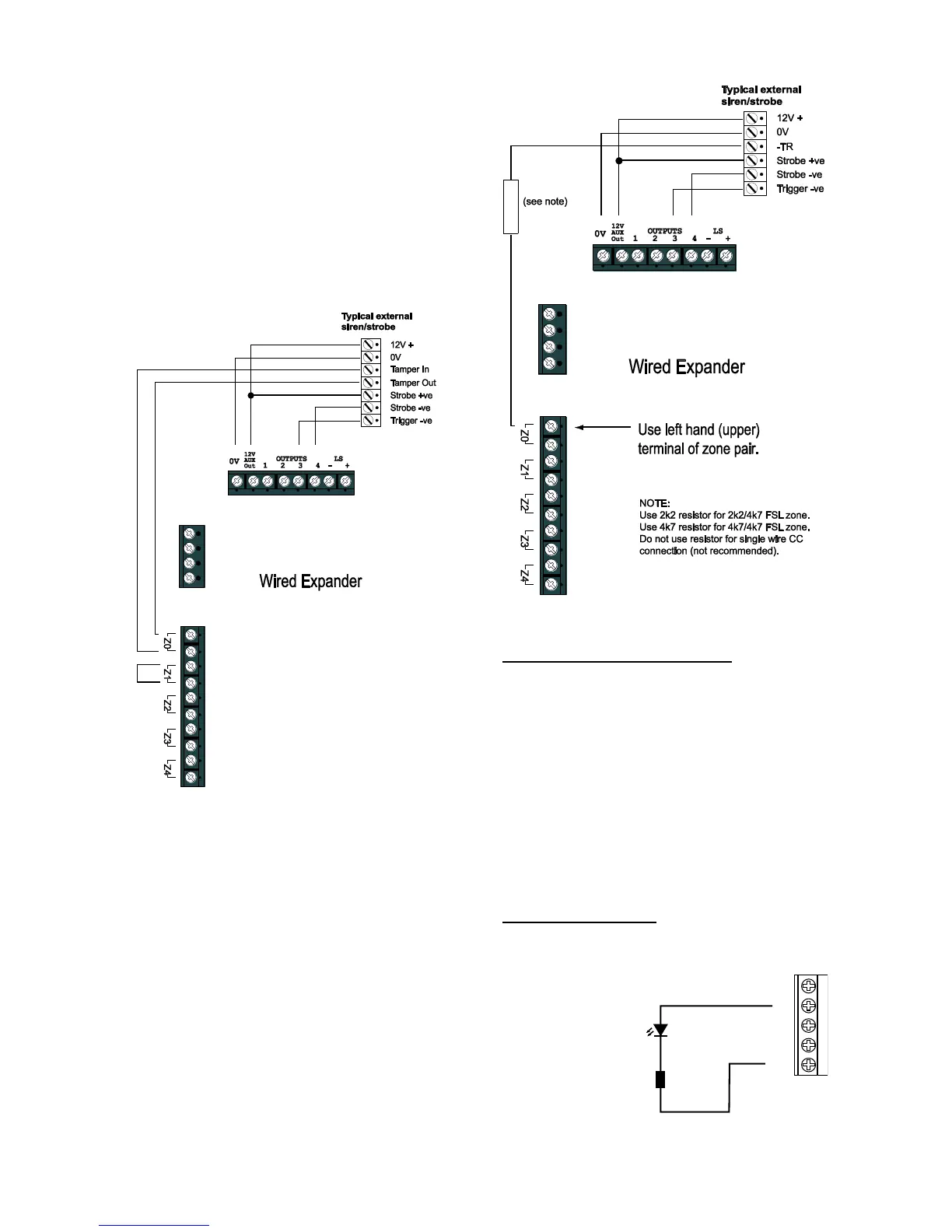
use the alarm contacts only and link the tamper
contacts together with a short length of wire.
In the Installer Menu, program the zone with a
type of “Tamper”. Program the outputs used to
trigger the siren and strobe with the appropriate
output types. See the i-onEX Range Engineering
Guide for more details.
Single Wire Tamper Return
If the external sounder provides a single –TR
connection, then use the zone type “Tamper
Return” for the zone terminals which receive the
connection at the expander.
Figure
Wiring External Sounder to Expander
FSL wiring. Connect –TR to the left hand terminal
of a zone connector, see Figure 42. (The left hand
terminal is the one next to the “Z” on the terminal
label.) The maximum length of wire is 50m when
using 2k2/4k7 or 4k7/4k7 FSL wiring and a single
core of standard 6-core alarm cable. Fit EITHER a
2k2 resistor if using 2k2/4k7 FSL, OR a 4k7
resistor if using 4k7/4k7 FSL. Do not use any
other FSL resistor combinations.
CC wiring Eaton’s Security Business does NOT
recommend that you use CC wiring for this
application. The maximum length of wire
allowable is only 6m. Instead Eaton’s Security
Business recommends using FSL wiring, as
described above.
Figure
Wiring –TR from External Sounder to a
Zone on the Expander.
Remote Loudspeakers (Optional)
If you wish to add a 16 Ohm wired Loudspeaker
unit, then connect it as shown in Figures 39 or 40.
The control unit provides connections for one
loudspeaker. Expanders provide connections for
one loudspeaker each. Do not connect another
loudspeaker in parallel. You may connect another
loudspeaker in series, but this will decrease the
maximum volume from the speakers.
Note: Loudspeakers are not warning devices as
described by EN50131-4. Although loudspeakers
may mimic alarm tones, they also give alert tones
and other progress tones when setting and
unsetting the alarm system.
Output on KEY-KPZ01
Figure 43 shows the wiring required to connect an
output the output terminal on the KEY-KPZ01.
Figure
RS485
0V 12V A B OP
1K0 Ohm Resistor
LED
(Light Emitting Diode)

 Loading...


