Connecting Wired Peripherals
Control Unit Wired Outputs
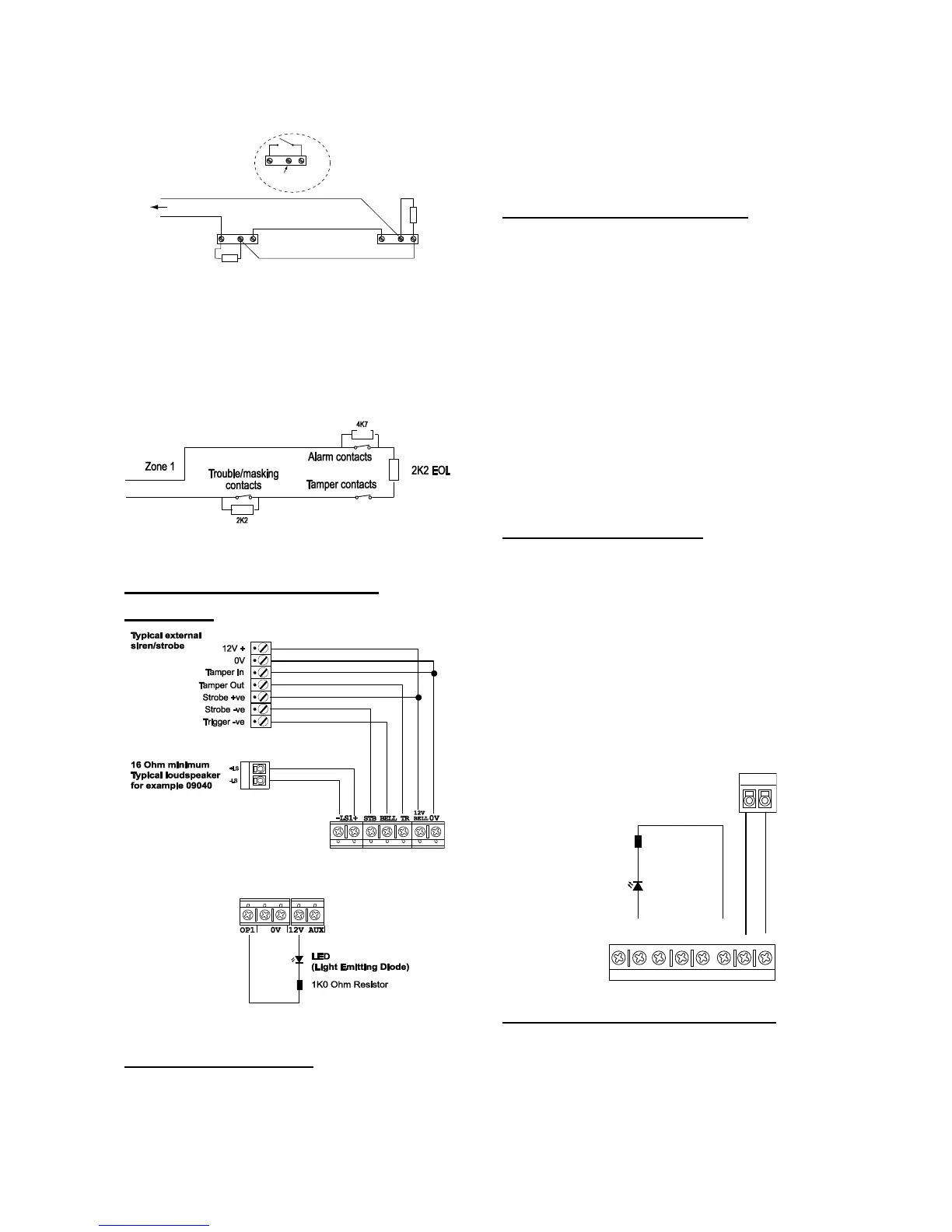
The control unit PCB provides one connector for
wired outputs. Outputs 1 is driven by a transistor,
and is capable of sinking a maximum 500mA
when active. By default output 1 is 0V when
active, +12V when inactive. If you wish to reverse
the polarity of this output see Changing the Polarity
of a Wired Output in the i-on Range Engineering
Guide.
Figure 39 shows an example of using the wired
outputs to drive an indicator LED.
Wired External Sounders (Optional)
Wired external sounders differ in their methods of
connection. Figure 39 shows an example of a
general method of using the outputs to connect a
wired sounder.
It is possible to program the TR terminal on the
control unit (see item 10 in Figure 3) as either CC
or FSL. Use Installer Menu – System Options – Panel
Tamper Rtn. By default the terminal is CC. If you
program the TR terminal as FSL then make sure
you connect a 2k2 resistor in series with the wire
to the sounder.
Note: If you do not wish to connect a wired
external sounder then leave TR programmed as
CC and make sure you link TR to 0V on the
control unit. This prevents the control unit
reporting Bell Tamper unnecessarily.
Wired Outputs on Expanders
Each EXP-W10 wired expander provides
connections for up to four transistor driven
outputs. Each output has a maximum rating of
500mA (but note that the bus may not be able to
supply this much current). By default the outputs
are 0V when active, +12V when inactive. If you
wish to reverse the polarity of these two outputs
see Changing the Polarity of a Wired Output in the
i-on Range Engineering Guide. Figure 40 shows an
example of using an expander output to drive an
LED.
Figure

 Loading...


