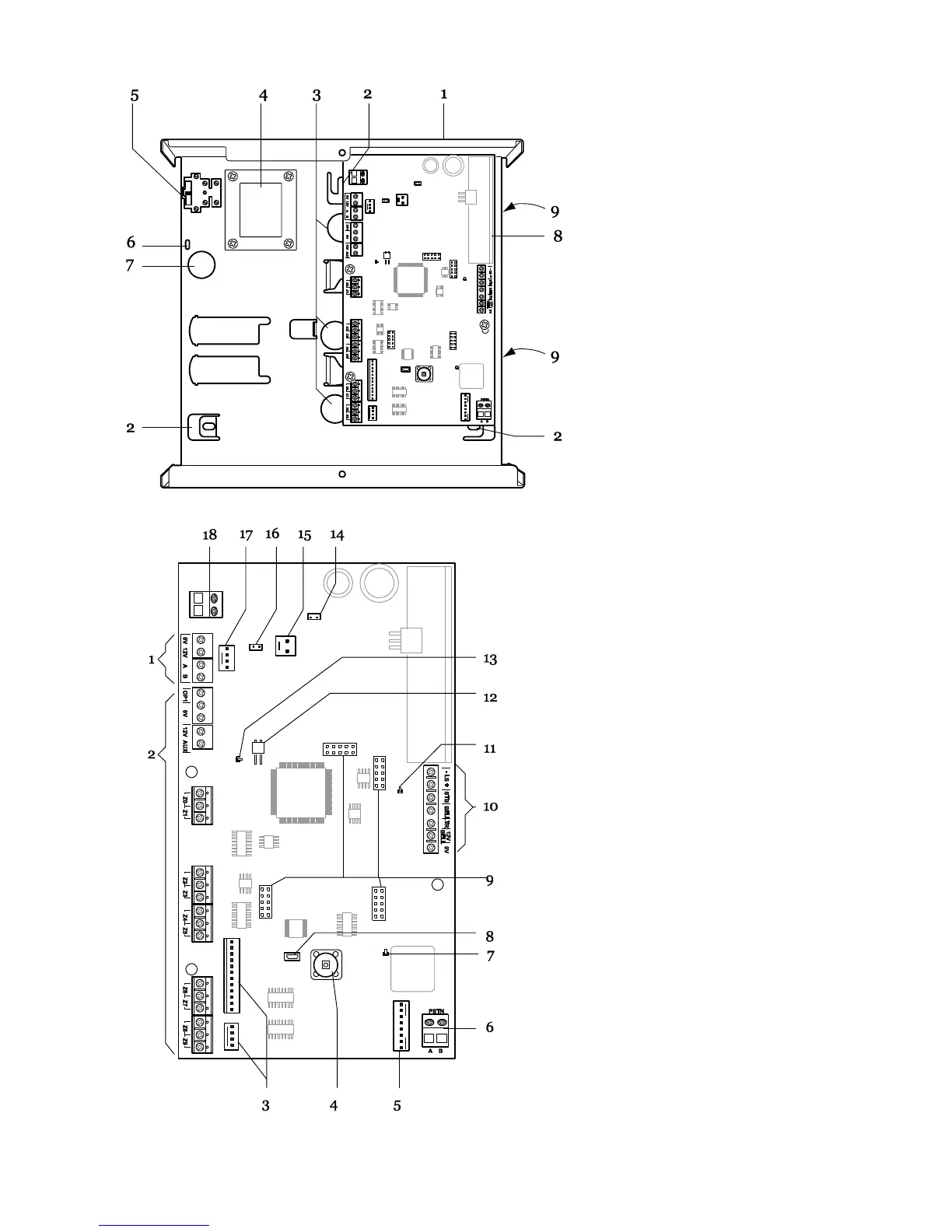
1. Case back.
2. Fixing holes.
3. Cable entry holes for detector
and keypad wiring.
4. Transformer.
5. Fused mains fuse and
connector block.
6. Mains cable anchor point.
7. Cable entry hole for mains
supply.
8. Printed circuit board (PCB).
9. Cable entry holes for
loudspeakers, siren/strobes and
communicators
1. Connectors for system bus.
2. Zone-, output-, and Aux power
connectors.
3. Plug by output connectors.
4. Tamper switch.
5. ADSL filter pins. (i-on30EXD only.)
6. On board communicator connections.
(i-on30EXD only.)
7. Off-hook LED. (i-on30EXD only.)
8. USB socket (Mini B).
9. Sockets for plug on module.
10.Loudspeaker, Bell and Strobe
connectors.
11. Comms activity LED. (i-on30EXD
only.)
12. Reset Codes pins.
13. Heartbeat LED.
14. Kickstart pins.
15. Battery connectors.
16. RS485 terminator.
17. Engineering keypad connector.
18. 20Vac connector.

 Loading...


