O & M Manual IM05805020K EATON LMR Plus
Effective September 2013 Electric Fire Pump Controllers
Page 13 www.chfire.com EATON CORPORATION
6. HISTORY, DIAGNOSTICS AND STATISTICS
The LMR Plus controller will record a number of items in
its memory to assist with troubleshooting of the system
and/or the fire pump controller.
These include system history, system statistics, and
controll
er diagnostics.
6.1 System History
The LMR Plus controller will record up to 10,000 alarm/
status messages in its memory that can be viewed on
the main display, saved to a USB storage device, or
viewed on the optional embedded webpage.
In order to view the messages on the display press the
up
or down arrow buttons from the main screen until the
display shows "Display Message History". Press the Ack.
Alarm button to view the message history. The display
will now show three messages at a time. Pressing the up
or down arrow buttons will allow navigation showing the
most recent message to the oldest message. Refer to
Appendix L for common messages and their meaning.
Refer to Section 7 to save the message history to a USB
sto
rage device or to view the message history on the
optional embedded webpage.
6.2 Statistics
The LMR Plus controller will record a number of
st
atistical points for a quick review of how the system
has been operating. The statistics can be viewed on the
main display, saved to a USB storage device, or viewed
on the optional embedded webpage.
In order to view the statistics on the display press the up
or down
arrow buttons from the main screen until the
display shows "Controller Statistics". Press the Ack.
Alarm button to view the statistics. The display will show
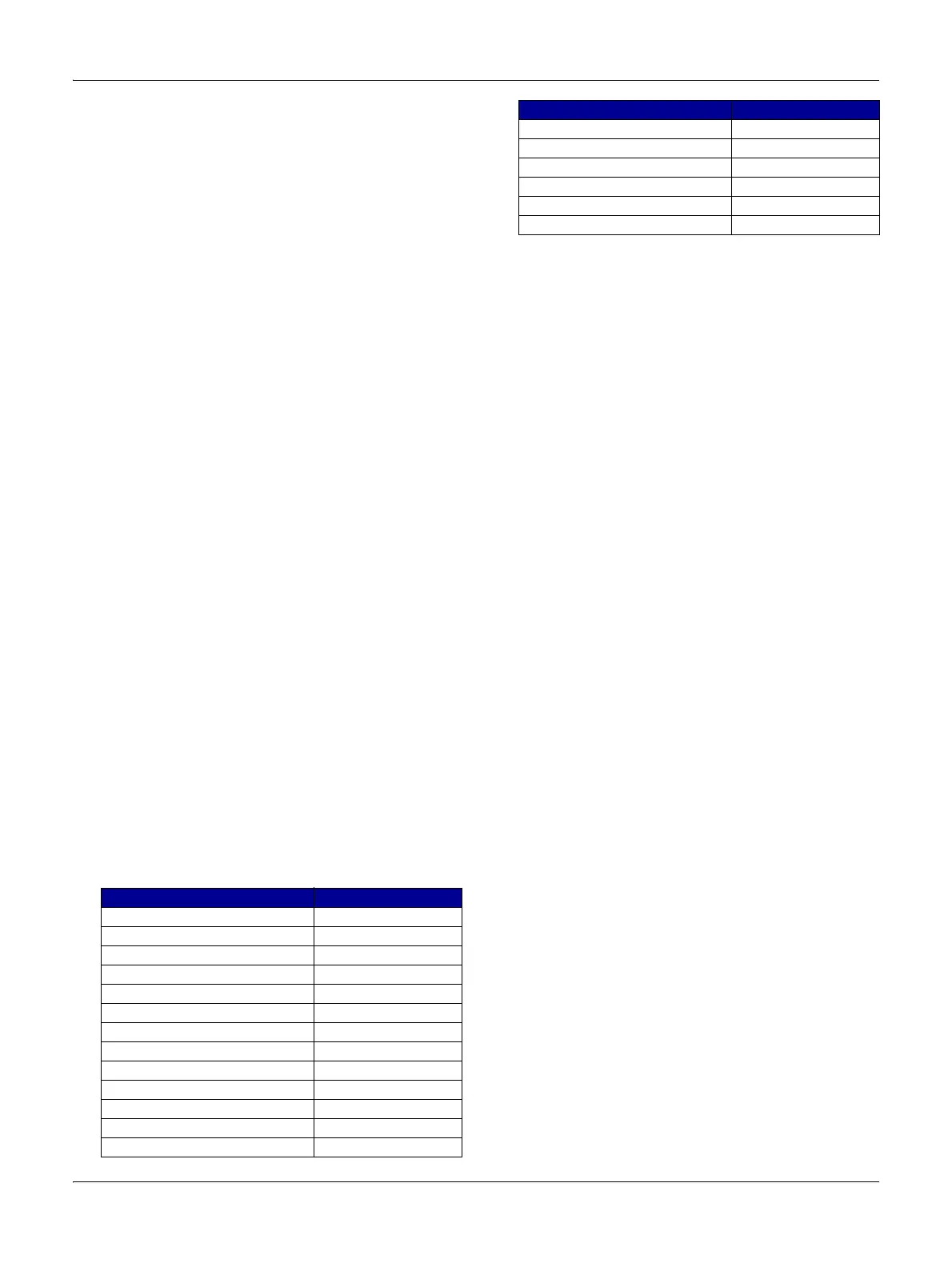
the statistics that the controller has recorded. Refer to
Table 5 for the statistics included with the controller.
Refer to Section 7 to save the co
ntroller statistics to a
USB storage device or to view the message history on
the optional embedded webpage.
Table 5 Controller Statistics
6.3 Controller Diagnostics
The LMR Plus controller has a number of diagnostic
po
ints that can be used to help in troubleshooting issues
with the controller. The diagnostics can be viewed on the
main display, saved to a USB storage device, or viewed
on the optional embedded webpage.
In order to view the diagnostics on the display press the
up
or down arrow buttons from the main screen until the
display shows "Controller Diagnostics". Press the Ack.
Alarm button to view the diagnostics. The display will
show the diagnostics. In order to navigate the
diagnostics use the up or down arrow buttons.
Note: T
he diagnostic information shall be provided to
personnel trained in the meaning of the values shown.
Diagnostic values that are recorded
are the current data
and time, the microprocessor's firmware version, Eaton's
shop order number, customer shop order number,
voltage readings, current transformer readings, pressure
sensor readings, input status, and output status.
Refer to Section 7 to save the controller diagnostics to a
USB storage device or to view the message history on
the optional embedded webpage.
7. COMMUNICATION
The LMR Plus controller is available with a number of
communication protocols that can be used for the
collection of information that the controller has seen.
A USB port is included standard. Optional
communi
cations ports are available for Ethernet,
Modbus and a Printer.
7.1 USB
The USB port is used to download the message history,
control
ler statistics, controller diagnostics, and status to
a USB storage device. The USB port can also be used to
upload custom messages, additional languages, and
update the microprocessor firmware.
The USB memory device must meet the following
requ
irements:
Maximum m
emory size: 2GB
USB
1.0 or 2.0
Formatted with Fat 16 protocol.
Statistic Range
Powered Time 000000.0-999999.9
Motor Run Time 00000.0-99999.9
Number of Calls to Start 00000-99999
Number of Starts 00000-99999
Last Motor Start Date & Time
Last Motor Run Time 0000.0-9999.9
Last Low Pressure Start Date & Time
Minimum System Voltage Unlimited
Maximum System Voltage Unlimited
Minimum System Frequency Unlimited
Maximum System Frequency Unlimited
Minimum System Pressure Unlimited
Maximum System Pressure Unlimited
Last System Startup Date & Time
Last Phase Failure Date & Time
Last Phase Reversal Date & Time
Last Locked Rotor Trip Date & Time
Maximum Run Current Unlimited
Last Locked Rotor Current Unlimited
Statistic Range

 Loading...


