O & M Manual IM05805020K EATON LMR Plus
Effective September 2013 Electric Fire Pump Controllers
EATON CORPORATION www.chfire.com Page 14
Information Download
In
order to download the history, diagnostics,
statistics, and status, install a USB storage device
into the USB port on the display board. With the
power on, press the Data | Print button. The first
selection is "Save to USB". Press the Ack. Alarm
button and the controller will save the information to
the USB storage device.
Th
ere will be five (5) files saved to the disk drive.
Refer to Table 6 for the file nomenclature.
Table 6 File Nomenclature
Th
e .csv file is a comma separated values file that
can be opened using standard spreadsheet, word
processor, or database programs. The .txt files can
be opened using standard text viewers.
Custom Message Upload
Th
e LMR Plus controller has the ability to store and
use up to ten (10) custom messages that can
appear based on a specific date, time, alarm or
status condition.
Refer to Appendix J to upload and enable the
custom messages.
Refer
to Section 8 for the creation of the custom
message file.
Firmware Update
Con
tact the factory or an authorized trained
representative for assistance.
Language Upload
Con
tact the factory or an authorized trained
representative for assistance.
7.2 Embedded Webpage *
The controller has a built-in webpage that can be used to
view the
main display of the controller and its current
status.
* COM Option must be ordered for this function.
Contact the factory or an authorized trained
represe
ntative for assistance in accessing the webpage.
7.3 RS485 Serial Port *
An optional RS485 serial port can be provided for
communi
cation to various external software programs
including Modbus.
*COM Option must be ordered for this function.
7.4 RS232 Serial Port *
This optional port is used with the optional printer (X1) to
initiate
a print cycle.
*COM Option must be ordered for this function.
8. CUSTOM MESSAGES
In order to upload custom messages to the controller a
file needs to be created. This section outlines the file
format and trigger points required to use the custom
messages.
All that is required to create the
custom message file is a
standard spreadsheet program. Specific software is not
required.
Ten (10) custom messages can be saved in the file and
up
loaded to the controller for use. Each message will be
entered in the first ten (10) rows of the spreadsheet. Do
not use the top row as a heading row.
There are five (5) trigger points that can be used. They
include specific date and time range, number of pump
start events, number of hours run, specific alarms, or
common alarm.
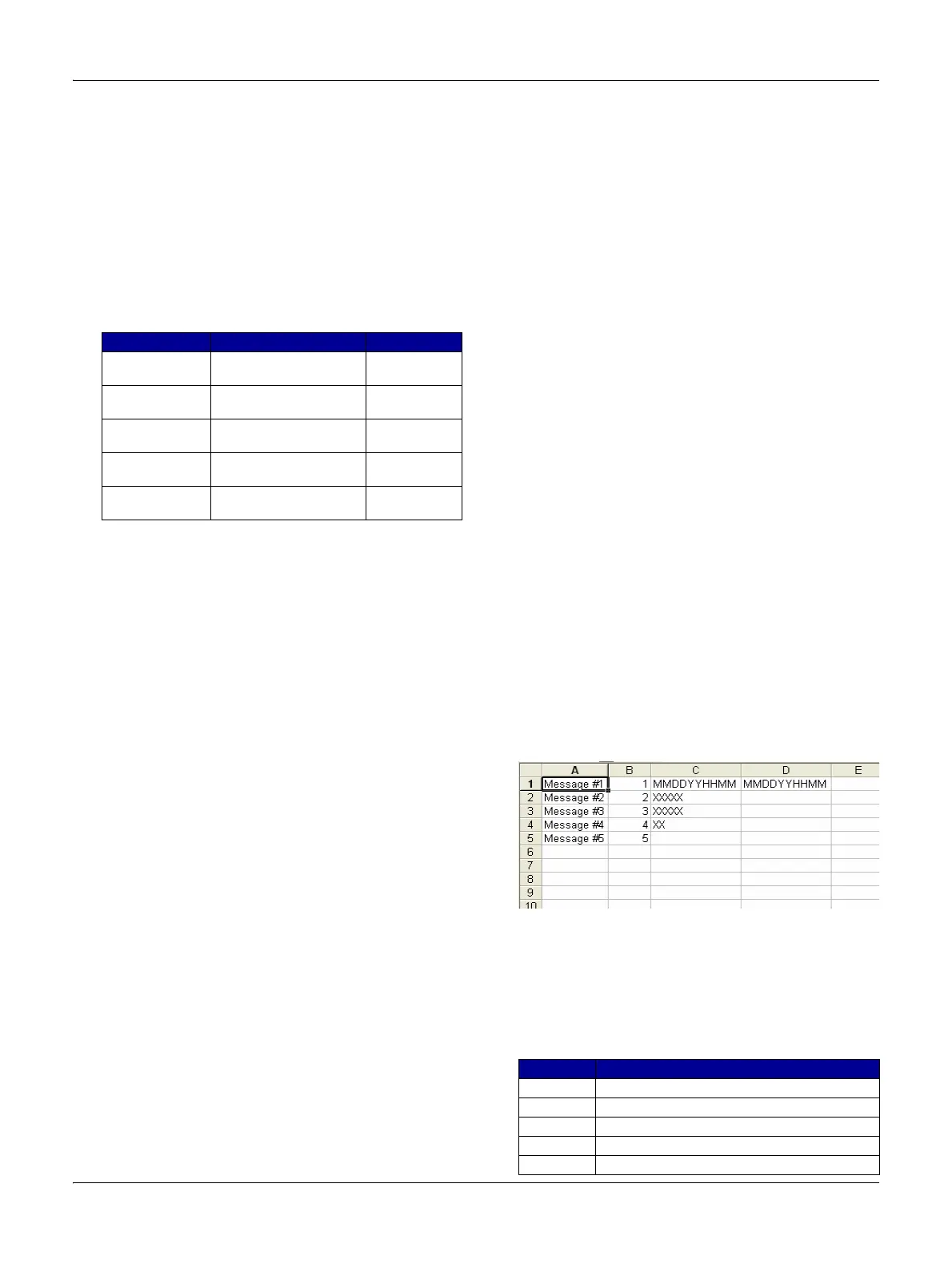
Figure 1 shows examples of the custom messages and
ho
w the file needs to be laid out. Following is a
description of each column and the data required to be
entered in the column.
Figure 1 Custom Message Examples
Column A contains the message that will scroll along the
fourth l
ine of the display. The message can be up to one
hundred (100) characters in length.
Column B contains the message type reference number.
Refer to
Table 7 for the message types.
Table 7 Custom Message Types
File Nomenclature Description
ARC00000.csv ARC=Archive
00000=Serial number
Message
history
STC00000.txt STC=Statistics
00000=Serial number
Controller
statistics
DIA00000.txt DIA=Diagnostics
00000=Serial number
Controller
diagnostics
STA00000.txt STA=Statistics
00000=Serial number
Controller
status
CON00000.txt CON=Configuration
00000=Serial number
Controller
configuration
Number Description
1 Specific date and time range
2 Number of pump start events
3 Number of hours run
4 Specific alarms
5 Common Alarms

 Loading...


