O & M Manual IM05805020K EATON LMR Plus
Effective September 2013 Electric Fire Pump Controllers
Page 29 www.chfire.com EATON CORPORATION
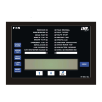
APPENDIX L: ALARM/STATUS MESSAGES
Message Description
ATS IN EMERGENCY The automatic transfer switch is in the emergency position
ATS IN NORMAL The automatic transfer switch is in the normal position
DELUGE VALVE START The controller started the motor after it received a deluge valve start signal
EMERGENCY START The emergency start handle was pressed in and the motor started
FAIL TO START There was a call to start the motor, however, the amperage draw did not reach 20% of the
programmed motor full load amps
FAIL TO STOP If the amperage draw has not dropped below 20% of the programmed motor full load amps
two (2) seconds after a stop command, this alarm will be triggered
FREQUENCY OK The system frequency has come back into normal operating levels and the alarm has been
cleared
GENERATOR DISCONNECT The isolation switch on the automatic power transfer switch is in the open position
HIGH PRESSURE The system pressure is above the programmed high pressure alarm set point
INTERLOCK OFF The interlock signal has been removed
INTERLOCK ON The interlock signal has been received
INTERLOCK SHUTDOWN The pump has been shutdown due to an interlock signal
JOCKEY RUNNING The jockey pump running signal has been received
JOCKEY STOPPED The jockey pump running signal has been removed
LOAD SHED CLOSED The load shed timer has started timing and the load shed output has closed
LOCAL START The start pushbutton on the enclosure flange was pressed initiating a start sequence
LOCAL STOP The stop pushbutton on the enclosure flange was pressed initiating a stop sequence
LOCKED ROTOR TRIP The controller has tripped on the built in locked rotor over current protection
LOW FOAM SHUTDOWN The controller has shutdown after receiving a low foam level signal
LOW PRESSURE The system pressure has dropped below the programmed pressure start point
LOW PRESSURE ALARM The system pressure has dropped below the programmed low pressure alarm point
LOW PRESSURE OK The system pressure has risen above the programmed pressure stop point
LOW PRESSURE START The pump has started running because of a low pressure condition
LOW ROOM TEMPERATURE The controller has received a low room temperature signal
LOW SUCTION The controller has received a low suction signal
LOW SUCTION SHUTDOWN The controller has shutdown because of low suction
MENU ENTERED The menu system was entered by a user
MOTOR OVERLOAD The amperage draw has exceeded 125% of the programmed motor full load amps
OV PHASE AB The voltage measured between phase A and B has exceeded the programmed
overvoltage alarm set point
OV PHASE BC The voltage measured between phase B and C has exceeded the programmed
overvoltage alarm set point
OV PHASE CA The voltage measured between phase C and A has exceeded the programmed
overvoltage alarm set point
OVER FREQ The system frequency has exceeded the programmed over frequency set point
PHASE A FAILURE The controller has detected a phase failure on phase A
PHASE A OK The phase failure alarm detected on phase A has been cleared
PHASE B FAILURE The controller has detected a phase failure on phase B
PHASE B OK The phase failure alarm detected on phase B has been cleared
PHASE C FAILURE The controller has detected a phase failure on phase C
PHASE C OK The phase failure alarm detected on phase C has been cleared
PHASE REVERSAL The controller has detected a phase reversal on the system voltage
PHASE REVERSAL OK The phase reversal alarm has been cleared
PRESSURE = 000 System pressure readings the controller has recorded
PUMP RUNNING The amperage draw on the motor has reached at least 20% of the programmed motor full
load amps
PUMP START The pump has started via a pump start signal
PUMP START OFF The pump start signal has been removed

 Loading...