O & M Manual IM05805020K EATON LMR Plus
Effective September 2013 Electric Fire Pump Controllers
Page 5 www.chfire.com EATON CORPORATION
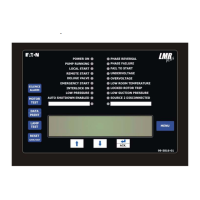
Phase Failure, Fail to Start, Undervoltage,
Overvoltage, Low Room Temperature, Locked Rotor
Trip, Low Suction Pressure, Auto Shutdown
Enabled, Source 2 Disconnected and two (2) user
defined LEDs.
There are nine input functions accessible via the
push
buttons:
Sile
nce Alarm
Motor Test
Data | Print
Lamp Test
Reset | Save/Exit
Up
Down
Ack. Alarm
Menu
A four-line, 40-character alphanumeric LCD Display
modul
e is used to display all LMR Plus monitored
parameters, set points, and messages in easy to read
formats. The display has a green high contrast
background that allows clear visibility of any information
displayed. The display is continuously lit for clear
visibility under poorly lit or no light conditions.
Seven different displays can be presented via the LCD
display:
S
tatus Display
Set Points Display
Statistics Display
Diagnostics Display
Configuration Menu
Data/Print Menu
Message History Display
The "Home" screen display will show the voltages and
current
s on all three phases, system frequency, system
pressure, and the current date and time. The fourth line
of the display will also indicate the time remaining on any
active timers, alarms without an associated LED, and
custom messages.
3.2.1 The LEDs
Po
wer On - This green LED will be illuminated
when there is power present in the controller and
the microprocessor board is powered up.
Pump
Running - This green LED will be illuminated
once the amperage draw in the controller exceeds
20% of the programmed motor full load amps.
Lo
cal Start - This green LED will be illuminated
when the pump is running after the start pushbutton
on the flange has been depressed.
Remote S
tart - This green LED will be illuminated
when the pump is running after receiving a start
signal on the remote start input.
Delu
ge Valve - This green LED will be illuminated
when the pump is running after receiving a start
signal from special starting equipment. This is a
normally closed contact that is required to be
opened to start.
Emer
gency Start - This green LED will be
illuminated when the pump is running after the
emergency start handle has been depressed and
the micro-switch has been activated.
In
terlock On - This green LED will flash when the
interlock input is received, signaling that another
controller or device has locked out the controller.
L
ow Pressure - This green LED will flash when the
system pressure has dropped below the
programmed low-pressure set point. If the pump is
running due to a low-pressure condition, this LED
will be fully illuminated.
Auto Shut
down Enabled - This Green LED will be
illuminated when the Auto Shutdown function is
enabled.
Pha
se Reversal - This red LED will be illuminated
when the controller senses that the input voltage
lines are reversed and there is a risk of operating
the pump in the reverse direction.
Pha
se Failure - This red LED will be illuminated
when at least one of the three phases coming into
the controller is missing or the voltage is abnormally
low.
Fail To Start - This red LED will be illuminated if the
amperage draw has not reached 20% of the motor
full load amps after the programmed fail to start
timer has timed out.
Und
ervoltage - This red LED will illuminate when
the system voltage is below the programmed
undervoltage alarm.
Overv
oltage - This red LED will illuminate when the
system voltage is above the programmed
overvoltage alarm.
L
ow Room Temperature - This red LED will
illuminate when the low room temperature signal
has been received. A thermostat can be supplied as
option R4.
L
ocked Rotor Trip - This red LED will illuminate
when the controller has tripped in a locked rotor
condition.
L
ow Suction Pressure/Low Foam Level - This red
LED will illuminate when the low suction pressure
signal has been received. A low suction pressure
switch can be added to the controller as option P7.
Sou
rce 2 Disconnected - This red LED will
illuminate if the main disconnect switch on a transfer
switch controller is turned off while the controller is
energized.

 Loading...