Parameters
M-Max Series Adjustable Frequency Drive MN04020003E—October 2013 www.eaton.com 79
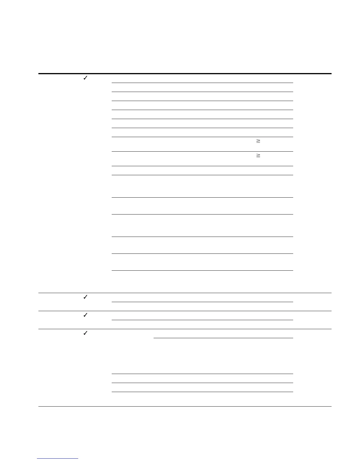
Digital Outputs, continued
PNU ID
Access
RUN Value/Range Description
Factory Setting
(P1.3)
P5.1 313 13 Overtemperature signal 2
14 Overcurrent control active
15 Overvoltage control active
16 PLC sequence control active
17 PLC sequence control, single step completed
18 PLC sequence control, program cycle completed
19 PLC sequence control, pause
20 Counter, value 1 reached. The counter value is the trigger
value set at P3.21 and can be reset by activating P3.24
21 Counter, value 2 reached. The counter value is the trigger
value set at P3.22 and can be reset by activating P3.24
22 RUN message active
23 Analog minimum reference error
Message if the setpoint signal (life zero) of AI1 and/or AI2 is
below 4 mA- or 2V (P2.1 = 1, P2.5 = 1)
24 LOG function fulfilled
Message if the logical operation of P13.3 is fulfilled (LOG = 1)
25 PID controller, actual value monitoring
Message if the actual value is within the hysteresis set at P9.15
and P9.16
26 External brake actuated
Switch threshold: set value of P12.8
27 Current monitoring
Switch threshold: set value of P5.8
28 Fieldbus, remote output
The assigned digital output is written directly to the general
control word (ID 2001, bit 13)
P5.2 314 — RO2 signal (relay output 2) 3
Like P5.1 Assignment of the function
P5.3 312 — DO Signal (Digital Output) 1
Like P5.1 Assignment of the function
P5.4 315 — Frequency monitoring 1 0
Monitoring of the selected frequency range
Actuate output if frequency is below or above Frequency
monitoring 1 reference value defined by P5.5.
A monitoring message can be implemented via the digital
outputs (P5.1, P5.2, P5.3 = 10)
0 Deactivated
1 0.00–P5.5 Hz frequency is below reference P5.5
2 P5.5–P6.4 Hz frequency is above reference P5.5
(P6.4 = maximum frequency)
 Loading...
