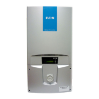
Do you have a question about the Eaton MMX34AA5D6N0-0 and is the answer not in the manual?
Key safety steps before starting installation procedures.
Warnings and precautions regarding high voltage.
General safety advice and critical warnings.
Critical warning about high voltage hazards.
Covers multiple safety points before installation.
Covers warnings related to voltage, wiring, ESD, and components.
Safety guidelines for motor operation and parameter settings.
Warnings related to automatic restart and start signals.
Guidelines for choosing the correct frequency inverter based on motor and application.
Defines the intended applications and correct usage of the device.
Recommendations for maintaining device performance and lifespan.
Information on support contact and warranty terms.
Guidance on connecting to various electrical power networks and voltage considerations.
Details on connecting the inverter to AC power networks.
Information on standardized input voltages and frequency ranges.
Safety procedures for electrical installation, fuses, and cable cross-sections.
Guidance on selecting appropriate fuses and cable dimensions.
Explanation of Residual Current Devices and their importance.
Methods for ensuring electromagnetic compatibility in drive systems.
Key considerations for motor selection and parallel motor applications.
General recommendations for selecting three-phase asynchronous motors.
General guidelines for installing the frequency inverter.
Specific requirements for EMC-compliant installation.
EMC measures for installation within control panels.
Proper grounding procedures for the system and components.
Guidelines for effective cable shielding connections.
Detailed instructions for electrical wiring and connections.
General connections for the frequency inverter in the power section.
Wiring diagram for three-phase AC input.
Identification of power section connection terminals.
Procedures for establishing a proper protective ground connection.
Diagrams and settings for analog setpoint inputs AI1 and AI2.
Configuration of transistor digital outputs.
Configuration of relay digital outputs.
Block diagrams illustrating the M-Max frequency inverter's internal structure.
Block diagram for MMX11 series inverters.
Block diagram for MMX12 series inverters.
Block diagrams for MMX32, MMX34, and MMX35 series.
Pre-operation verification checklist for proper setup.
Critical warnings and cautions during device operation.
Steps for initial commissioning using factory defaults.
Comprehensive list of fault and warning codes, causes, and instructions.
How to set the operation and function of digital inputs.
Configuration of analog voltage signal outputs.
Setting operating conditions for the M-Max frequency inverter.
Configuration of acceleration and deceleration ramp times.
Setting protective functions to safeguard the drive system.
Configuration of motor temperature protection algorithms.
Setup and configuration of the integrated PID controller.
How to enable or disable PID control using digital inputs.
Setting fixed frequency values for program sequences.
Configuring voltage/frequency control procedures.
Setting various braking functions like DC braking and mechanical braking.
Parameters for configuring a second motor.
A guide to parameters for quick initial configuration.
Parameters for controlling drive functions like acceleration and deceleration.
Parameters related to motor specifications.
Settings for motor and drive protection functions.
Configuration details for the PID controller.
Parameters for setting predefined operating frequencies.
Configuring voltage/frequency control procedures.
Parameters for controlling motor braking functions.
Parameters for configuring a second motor.
| Input Voltage | 480V |
|---|---|
| Output Voltage | 0-480V |
| Horsepower | 5 HP |
| Enclosure | NEMA 1 |
| Frequency | 50/60 Hz |
| Efficiency | 98% |
| Protection Rating | IP20 |
| Communication Interface | Modbus RTU |
| Phase | 3 |
| Cooling Method | Fan |


