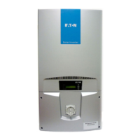
Do you have a question about the Eaton MMX12AA1D7F0-0 and is the answer not in the manual?
Critical steps to take before starting installation, including power disconnection and grounding.
Specific warnings and precautions related to working with high voltage components.
Presents a block diagram detailing internal components and connections of the M-Max frequency inverter.
Details how to connect and configure the inverter to different AC power networks.
Provides guidance on selecting appropriate fuses and cable cross-sections.
Explains the importance and type of RCDs required for frequency inverter installations.
Provides recommendations for selecting the correct motor for use with the frequency inverter.
Provides general instructions for installing M-Max frequency inverters, including IP ratings.
Illustrates the correct mounting positions and orientations for M-Max frequency inverters.
Covers necessary cooling measures and air circulation requirements for M-Max inverters.
Specifies the required air-cooling space and clearance dimensions around the frequency inverter.
Details the process and requirements for fastening the inverter using screws.
Details specific EMC measures for control panel installations, including grounding and cable routing.
Details the general connections for the frequency inverter in the power section.
Shows the typical three-phase input connection diagram for the frequency inverter.
Lists and explains the terminal designations used in the power section of the inverter.
Explains how to establish a proper ground connection for the frequency inverter.
Describes the arrangement of control signal terminals under the front cover flap.
Provides crucial Electrostatic Discharge (ESD) precautions for handling control signal terminals.
Lists the functions and electrical connection data for all control signal terminals.
Provides a checklist to ensure all steps are completed before placing the frequency converter into operation.
Lists operational hazard warnings and cautions to observe during inverter use.
Details factory settings for commissioning the inverter using control signal terminals.
Explains how faults are indicated and how to acknowledge them.
Details the procedure for acknowledging and resetting error messages.
Provides a list of fault/warning messages, their causes, and instructions.
Explains how to acknowledge and reset error messages using the operating unit.
Guides the user through the general process of selecting and setting parameters.
Guides users through the quick configuration process for essential drive settings.
Details how to adapt analog inputs AI1 and AI2 for setpoint and process variable signals.
Covers setting the operation and function of digital inputs DI1 to DI6.
Details parameters for digital outputs, including relay and transistor types.
Covers parameters for controlling drive functions like remote source and speed reference.
Explains how to set acceleration and deceleration times for the drive.
Enables cyclical program sequences using fixed frequency setpoints.
Details parameters for fixed frequencies and their associated run times.
Covers parameters related to braking functions like DC braking and brake chopper.
Explains the quick configuration process initiated upon first power-up or after factory reset.
Guides users through the initial parameter setup using the quick start assistant.
Details parameters related to analog inputs, including signal ranges and custom settings.
Lists parameters for digital inputs, covering start/stop logic, fixed frequencies, and resets.
Details parameters for analog outputs, including signal range, gain, and filter time.
Lists parameters for digital outputs, including relay and transistor outputs.
Covers parameters for controlling drive functions like remote source and speed reference.
Explains how to activate and configure the PID controller for closed-loop control.
Details parameters related to braking functions such as DC braking and brake chopper.
| Model | MMX12AA1D7F0-0 |
|---|---|
| Frequency | 50/60 Hz |
| Waveform | Sine Wave |
| Continuous Power Output | 12 kVA |
| Cooling | Fan |
| Protection Features | Overload, Overvoltage, Short Circuit |


