6
Section 1: Introduction
Series NRX with PXR – Type NF Low Voltage Power (Air) Circuit Breaker Instruction Manual MN013001EN May 2015 www.eaton.com
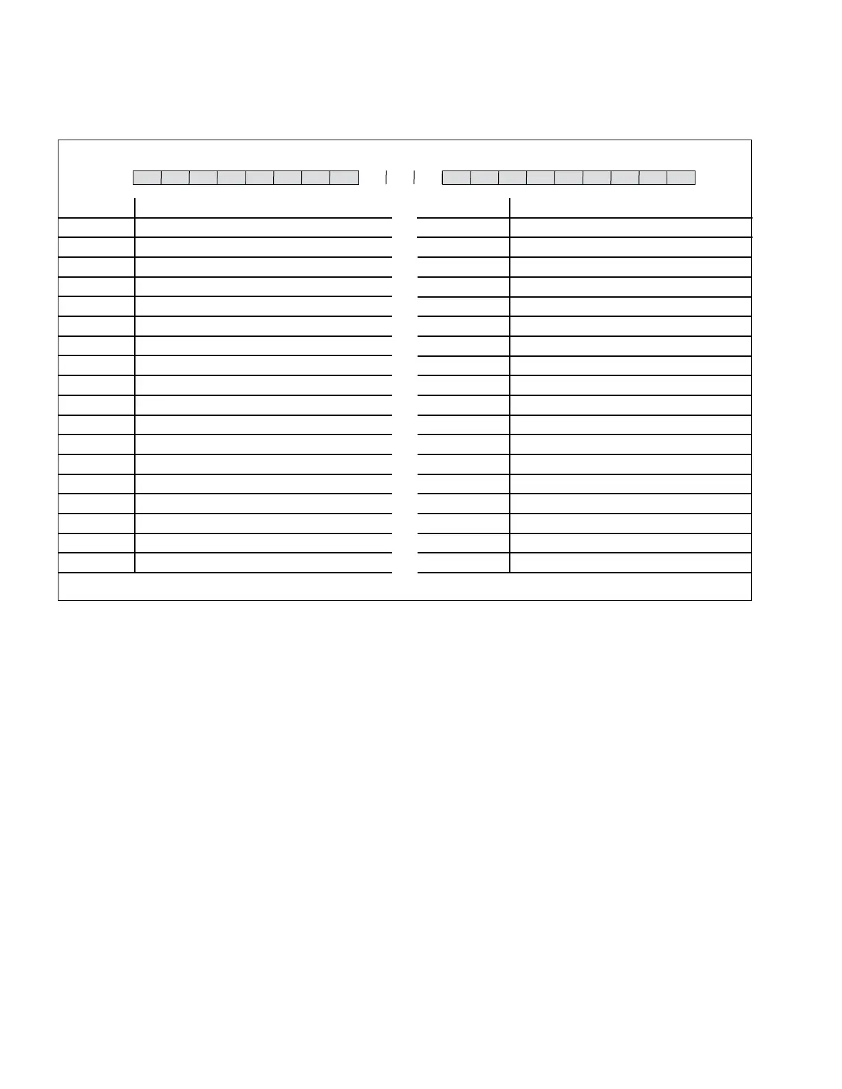
Figure 2A. Series NRX Type RF - Frame Cassette Catalog Numbering System.
NF Cassette Catalog Numbering System
Position 1-2 Cassette Family and Breaker Frame
NQ UL 1066 N-Frame
NY UL 489 N-Frame
NG IEC 60947-2 N-Frame - Global
NA IEC 60947-2 N-Frame - China
Position 3-4 Continuous Ampere Range
08 800 A (UL 1066)
12 800 - 1200 A (UL 489)
16 630 - 1600 A (IEC)
Position 5 Poles, Phasing (Facing Front of Breaker)
3 3-pole, ABC
4 4-pole, NABC
Position 6 Load Terminal Connections
F With Flat Tapped Pads Only
G With Vertical/Horizontal Bus Adaptor Kit (Short Style)
H With Front Connected Kit
N No Flat Tapped Pads or Cassette Stabs Inter Unit Only)
Position 7 Arc Hood
A Arc Hood Installed (Default)
Breaker Overview
Figures 3 through 6 highlight the main components that
make up a Series NRX breaker.
Drawout Breaker and Cassette
A drawout circuit breaker is used in combination with a dra-
wout cassette (Figures 3 and 4). Mounted on the drawout
breaker are the primary finger clusters and levering mecha-
nism. These components are located on the breaker to
allow Users easy access when performing product inspec-
tion or maintenance. The cassette provides all the neces-
sary drawout circuit breaker interfaces, including primary
and secondary connections. Standard flat terminal pads
on the rear of the cassette provide for a variety of primary
connection configurations. Optional primary adapters are
available for front and rear bus or cable connections. For
specific details and mounting instructions for primary adapt-
ers, refer to www.Eaton.com/seriesnrx.
Refer to Section 5 for mounting and installation dimensional
information. Electronic files of dimensional drawings for
customer use are available for download at www.eaton.
com/seriesnrx.
Position 8 Door Frame Gasket and Rejection Kits
B Door Kit Included (Default)
Position 9 TOC Switches (Truck Operated Cell)
N Not Included (Default)
Position 10 Shutters
N Not Included (Default)
S Included
Position 11 Secondary Contact Terminals Installed
N None
F Full Complement
B Defined by Breaker
C Common Options
Position 12 Future Use
N None
Position 13 Future Use
N None
Position 14 Cassette Shipping
C Cassette Only
B Breaker Shipped in Cassette
Fixed Circuit Breaker
A fixed circuit breaker is rigidly mounted in its structure with
no drawout feature. The circuit breaker is available in front
and rear-connected configurations (Figure 5).
The breaker can be mounted on a suitable horizontal mount-
ing surface using left and right-side mounting feet. A stan-
dard fixed circuit breaker is supplied with flat primary termi-
nal pads on the rear of the breaker that will accommodate a
variety of primary connection configurations.
Positions 1 2 3 4 5 6 7 8 9 10 11 12 13 14 15 16 17 18 19 20

 Loading...