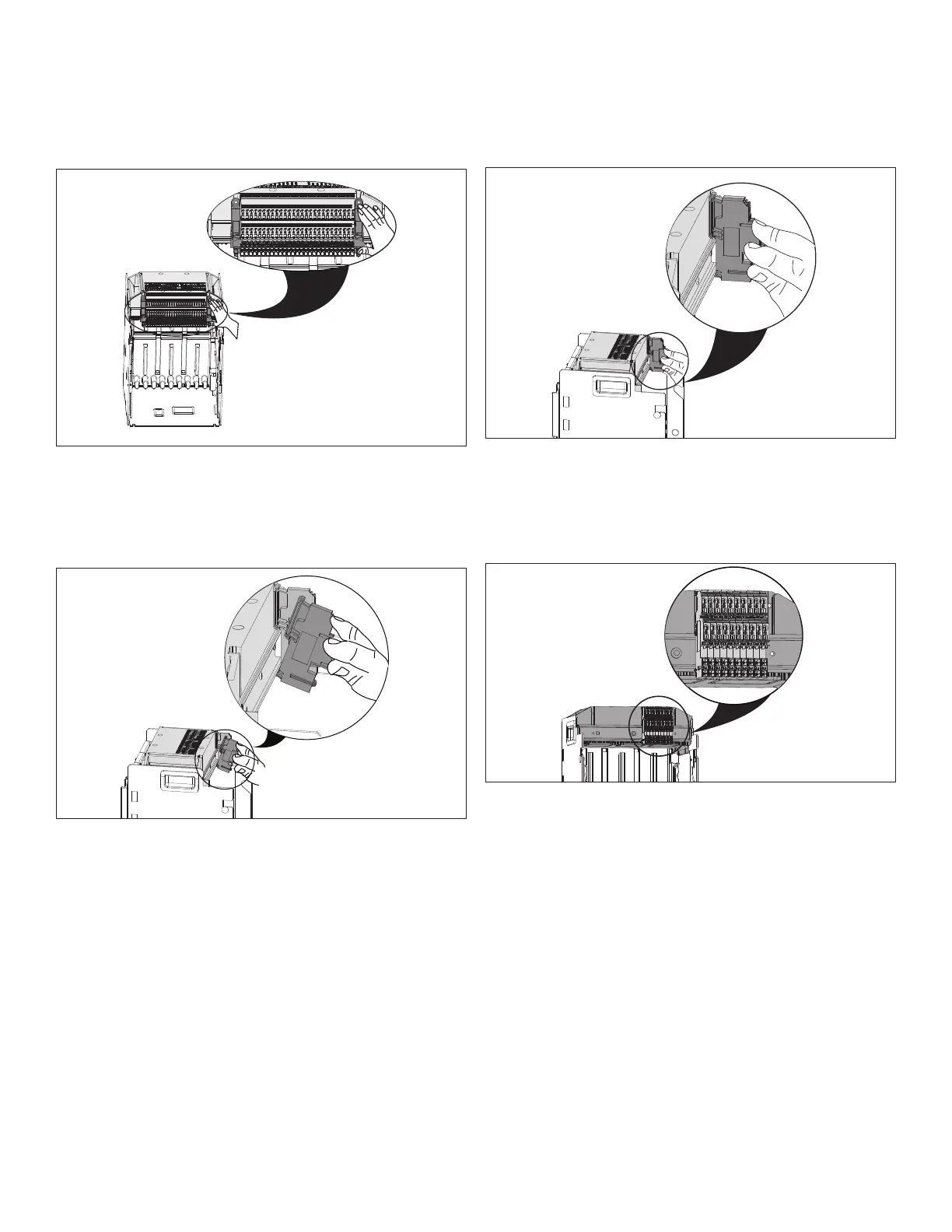
Figure 16. Step 3
Step 4: Connect the bottom part of the terminal block to the
lower part of the DIN rail. Ensure the terminal block is posi-
tioned accurately.
Figure 17. Step 4
Step 5: Snap the top part of the terminal block onto the upper
part of the DIN rail. Ensure the terminal block is still positioned
accurately.
Figure 18. Step 5
Step 6: Repeat Steps 4 and 5 until all terminal blocks are
mounted, and check to ensure they are positioned in the cor-
rect locations. A small number of DIN rail mounted terminal
blocks would look as shown.
Figure 19. Step 6
Step 7: Carefully put the terminal block alignment bracket
back into position by sliding it back into the DIN rail mounted
terminal blocks.
6
EATON CORPORATION www.eaton.com
Instructional Leaet IL01301037E
Effective December 2010

 Loading...