12
Installation and Removal Instructions
for Series NRX Spring Release, Latch
Check Switch and Motor Operator
EATON CORPORATION www.eaton.com
Instruction Leaet IL01301010E
effective January 2013
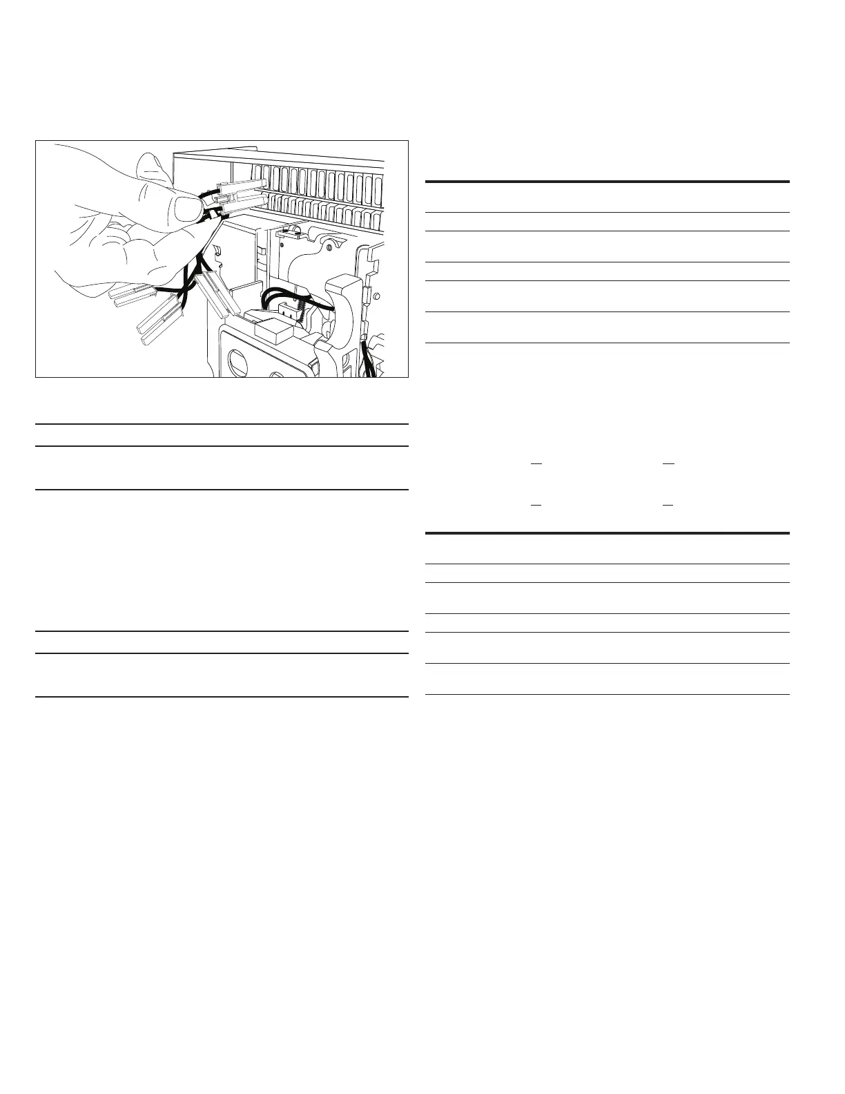
Figure 37.
1
2
Step 2
• IMPORTANT
TO REMOVE RIGHT AND LEFT ACCESSORY TRAYS OR ANY OTHER
ELECTRICAL ACCESSORY, THE APPROPRIATE ACCESSORY CONNECTOR PLUG
MUST FIRST BE DISCONNECTED.
Step 3: To remove an accessory connector plug on a drawout circuit
breaker, unplug it from its secondary plug housing. Refer to Item 2 and
Figure 31 under the heading “General information” in this section for
detailed assistance with the removal.
Section 10: Spring release/latch check/
motor operator testing
• IMPORTANT
BEFORE PERFORMING ANY TEST ACTIVITIES, LEVER A DRAWOUT CIRCUIT
BREAKER TO THE TEST POSITION. FOR FIXED TYPE CIRCUIT BREAKERS,
MAKE SURE PRIMARY CIRCUITS ARE DE-ENERGIZED.
Spring release testing
1. Verify that the circuit breaker is in the Open position. Charge the
breaker’s closing spring using the manual charging handle.
2. Apply rated voltage to the spring release and verify that the breaker
toggles to the Closed position.
Spring release with internal latch check switch testing
Place the circuit breaker in the different positions shown in Table 5 and
apply rated voltage to the spring release.
ote:N The voltage needs to be removed from the spring release before it can be
applied each time.
Table 5. Testing Sequence with Internal Latch Check Switch
Initial Breaker
Position Spring Release Result Final Breaker Position
OPEN,
discharged
Does not
actuate
No change
OPEN, charged Actuates Closed
CLOSED,
discharged
Does not
actuate
No change
CLOSED, charged Actuates Attempts to close again
Hold OPEN button,
discharged
Does not
actuate
No change
Hold OPEN button,
charged
Does not
actuate
No change
Spring release with external latch check switch testing
Place the circuit breaker in the different positions shown in Table 6 and
check the continuity between the leads shown in the table.
Table 6. Testing Sequence with External Latch Check Switch
Initial Breaker
Position
NF
Continuity Between Red (42)
and Black (41) Leads
RF
Continuity Between Red (56)
and Black (55) Leads
NF
Continuity Between Blue
(40) and Black (41) Leads
RF
Continuity Between Blue
(54) and Black (55) Leads
OPEN,
discharged
Yes No
OPEN, charged No Yes
CLOSED,
discharged
Yes No
CLOSED, charged No Yes
Hold OPEN button,
discharged
Yes No
Hold OPEN button,
charged
Yes No
Motor operator testing
1. Verify that the circuit breaker is in the open and discharged
condition. Apply voltage to the motor operator. Breaker charging
should initiate. Verify that the breaker flag changes state to indicate
the fully “Charged” condition, and that the motor operator has
stopped running.
2. Close the breaker and verify that the motor operator automatically
charges the breaker again.
3. Drawout breaker only: Remove voltage from the motor operator
and return breaker to the open and discharged condition. Hold the
levering access door open and apply voltage to the motor operator.
The operator should NOT charge the breaker. Release the levering
access door and verify that the operator charges the breaker.

 Loading...