6
Installation and Removal Instructions
for Series NRX Spring Release, Latch
Check Switch and Motor Operator
EATON CORPORATION www.eaton.com
Instruction Leaet IL01301010E
effective January 2013
Section 6: Motor operator general infor-
mation
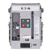
A motor operator is an electric motor assembly internally mounted in
the right-hand side of the circuit breaker (Figure 15). It charges the
closing springs electrically for remote or local operation. The motor
operator can be factory or field installed (Table 3 NF and Table 4 RF).
If a motor operator is being installed in the field, an optional spring
release device can also be installed. Instructions for the installation of
a spring release are provided in Section 2 of this document.
Figure 15.
Motor
Operator
Motor Operator Location
Section 7: Installation of motor operator
Proceed with the following 11 steps:
Step 1: Remove the four screws holding the front cover in place (two
on each side of the cover).
Figure 16. Step 1
Step 2: Remove the front cover. Pull down on the charging handle to
simplify removal.
Table 3. Motor Operator Ratings - NF
Control Voltage Frequency
Operational Voltage
(Range 85–110%)
Run Current
(Amperes) Typ. Inrush Current
Power
Consumed
(VA)
Max. Charge
Time (sec)
24 DC 20–26 6 325% 160 4
48 DC 41–53 3 500% 150 3
60 DC 51-66 2 350% 150 4
110–127 50–60 Hz 94–140 2 300% 280 3
110–125 DC 94–138 1 500% 150 3
208–240 50–60 Hz 177–264 1 1000% 280 4
220–250 DC 187–275 1 1000% 280 4
Table 4. Motor Operator Ratings - RF
Control Voltage Frequency
Operational Voltage
(Range 85–110%)
Run Current
(Amperes) Typ. Inrush Current
Power
Consumed
(VA)
Max. Charge
Time (sec)
24 DC 20–26 7 350% 200 6
48 DC 41–53 3 450% 175 6
60 DC 51-66 3 450% 225 6
110–127 50–60 Hz 94–140 3 300% 425 6
110–125 DC 94–138 2 375% 275 6
208–240 50–60 Hz 177–264 1.5 300% 400 6
220–250 DC 187–275 1 400% 250 6

 Loading...