2
Quick Start Guide IL02601011E
Effective October 2009
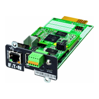
Power Xpert® Meter 2000 Gateway Card Kit
EATON CORPORATION www.eaton.com
Remove the Meter From Service
Turn power off at the breaker feeding the meter. There may be more
than one breaker. Use local safety procedures such as “Lock out/ Tag
out” to ensure the breaker(s) is not inadvertently energized.
Ensure the high power connections on the meter are de-energized.
Current sensing wires may be connected directly to the load by
•
simply passing the current carrying conductors (load or Current
Transformers) directly through the meter. There is no physical
connection to the meter.
Current sensing wires may be connected directly to the meter
•
by attaching the current carrying conductors to “current gills” or
quick connect terminals on the meter.
Then remove or disconnect the current sensing wires from the
meter.
H Warning!
Use caUtion to ensUre the cUrrent throUgh the cts is off or sUit-
able protection is in place to prevent contact With the leads from
the ct.
ensUre the control or logic poWer to the meter is de-energized. the
voltage at these terminals is the local ac voltage.
Disconnect Power Connections, CTs, and Modbus
Remove the large 13 position connector on the back of the meter. 1.
If the installation is being done on an operational meter, this 2.
connector must be removed before installing the Gateway Card.
Removing this connector will remove power to the meter. The
Gateway Card is not designed to be hot-pluggable (installed with
power on).
If an extra 13 position connector is not available, make note of 3.
where the wires are connected to the 13 pin connector. You will
need this information when re-connecting the wires. Then remove
the wires from the 13 position connector and replace the connector
into the meter.
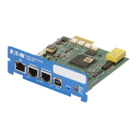
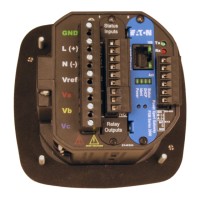
13 and 6 position connectorsFigure 1.
Remove Meter from Panel
When removing the meter keep the mounting hardware (screws,
washers, etc.) in a safe place for use when re-installing the meter.
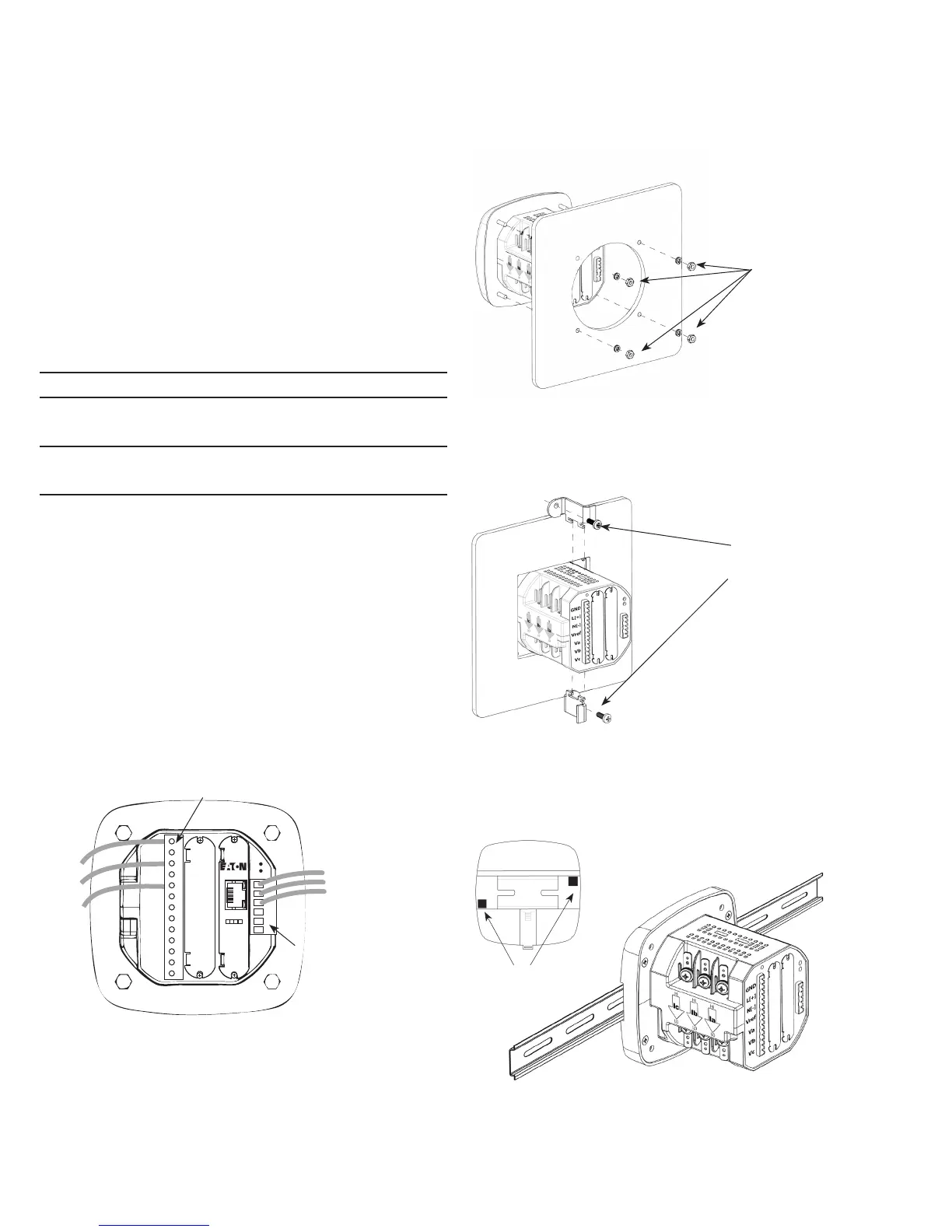
For ANSI installations remove the four nuts and washers.
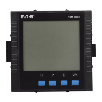
Removing the four nuts and washersFigure 2.
For DIN installations remove the two screws and mounting brackets.
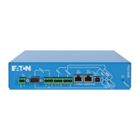
Removing the DIN mounting bracketsFigure 3.
For DIN rail installations pull down on the mounting clips to release
the meter.
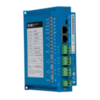
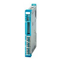
Transducer version of meter mounted on DIN railFigure 4.
Locate the Meter on the Bench
The installation procedure requires local power and an active
Ethernet connection. To provide power to the meter, it may be useful
13 position connector
GND
L(+)
N(-)
6 position network
connector
Four mounting
nuts and lock
washers
Mounting
brackets and
screws
Mounting clips
 Loading...