3
Quick Start Guide IL02601011E
Effective October 2009
Power Xpert® Meter 2000 Gateway Card Kit
EATON CORPORATION www.eaton.com
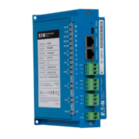
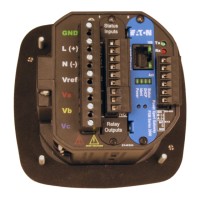
to build an Aux cable to GND, L(+) and N(-) using a 13 position con-
nector. This is particularly useful if installing many Gateway Cards.
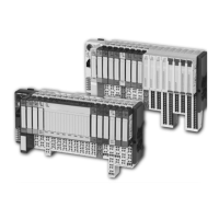
The Gateway Card must be installed in slot 2. If slot 2 is occu-
pied, remove the card in slot 2 and place it into slot 1. Otherwise,
remove the option card cover over slot 2. Retain the screws.
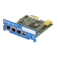
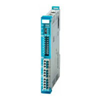
Install the Gateway Card
i
caUtion!
Use local electrostatic discharge protection or toUch a sUitably
groUnded metal sUrface to discharge any static electrical charge.
failUre to folloW these gUidelines coUld caUse damage to the
gateWay card.
Remove the Gateway Card from the protective wrap. 1.
Locate the MAC address printed on the card. Record it here. 2.
MAC Address:_________________________________________
The MAC address is on a small label and consists of 14 letters and
numbers. It looks something like: 0020808500EF
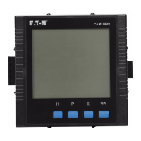
Another MAC address label is included in that kit and should be 3.
applied to the flat area on top of the meter (above the meter’s infor-
mation label).
Area for MAC address labelFigure 5.
Verify the switch settings on the card. All switches should be in 4.
the off position.
Card Switches Shown in the Off Position Figure 6.
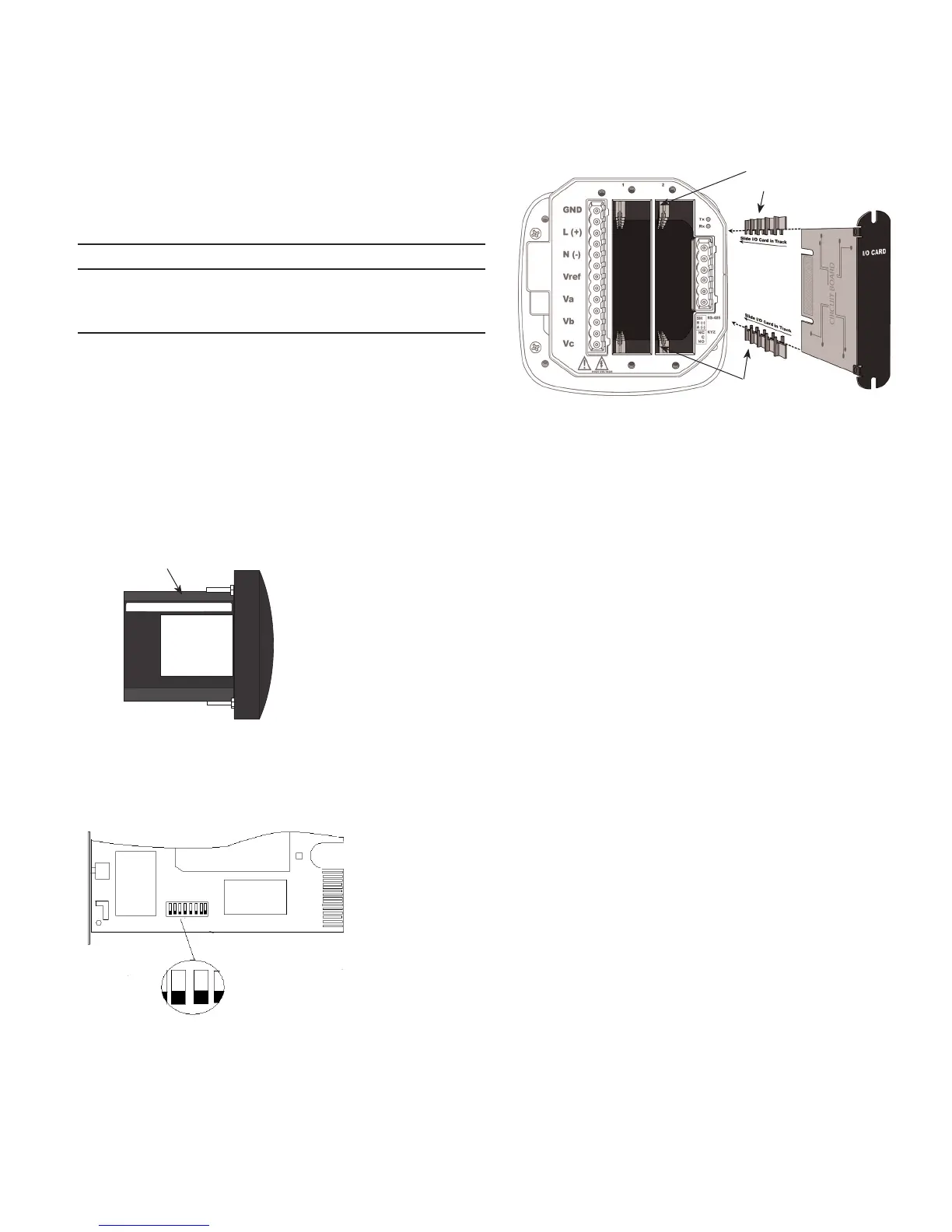
Insert the Gateway Card into meter slot 2 using the meter’s built-5.
in card guides (see the following figure). Use care to correctly locate
the card in the guides. Slide the card carefully into the meter until it
stops. Gently push on the card until it “clicks” into place.
Install Gateway Card into slot 2Figure 7.
Secure the card by replacing the screws removed while removing 6.
the cover.
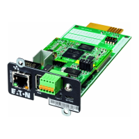
If available, connect the building Ethernet cable to the jack on the 7.
Gateway Card. Otherwise use a local Ethernet equipped PC and the
seven-foot Ethernet cable shipped with this kit.
If available, connect the Modbus connector (6 position connector) 8.
that is attached to the Modbus network.
Attach the power cord. If an AUX power cord was assembled 9.
then insert the connector into the socket. Otherwise connect GND,
L(+) and N(-) to the 13 position connector as indicated in the figure
on page 2.
Apply power to the power cord.10.
There are four lights (LEDs) on the Gateway Card labeled Status, 11.
DHCP, Ident, and Power. When power is applied all the lights should
be on for a few seconds and then the right (Power) light should
illuminate. This indicates the card has power and is running. The left
(Status) light will illuminate after 30 to 60 seconds.
There are two lights (LEDs) located on the Ethernet cable jack. 12.
If the Ethernet cable has an active Ethernet connection the light
labeled Act may be flickering. The light labeled 100 will be lit if the
Ethernet connection is active at 100 Mbps.
Put MAC address
label here
I/O Card Guide
Track
I/O Card Guide
Track
 Loading...