www.eaton.com IM02601004E Page 11
2 Quick Start Guide for the Meter Module
2.4. Establishing Communications between the Meter Module and the Optional Graphic Display
Module
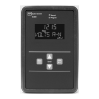
1. Establishing communication between the Graphic Display Module and Meter Module:
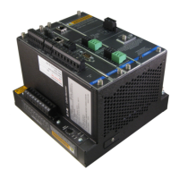
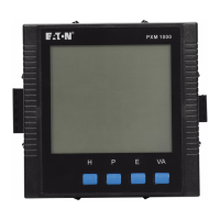
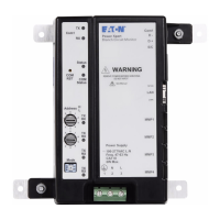
A. Using an RS485 cable, connect COM 0 (Figure 4) on the back of the Display Module
to COM 0 (Figure 5) found on the Meter Module (RS485 Comms). See table below and
the Cable Specications Table for wiring.
Display PXCM
Description Terminal Cable Terminal
DA DG1-1 TP CM5-1
DB DG1-2 TP CM5-2
SH DG1-3 SDW CM5-3
TP=Twisted Pair
SDW = Shield Drain Wire
B. Connect CM6 (Figure 5) located on the CM card to DG2 (Figure 4) on the Display
Module to supply power (24V) to the Display Module. See table below for wiring.
Display PXCM
Description Terminal Cable Terminal
SH DG2-1 OSCS CM6-1
24+ DG2-2 TP CM6-2
COM DG2-3 TP CM6-3
Gnd DG2-4 To local panel ground
OSCS=Optional Separate Cable Shield
(OSCS used for separate power and data cables)
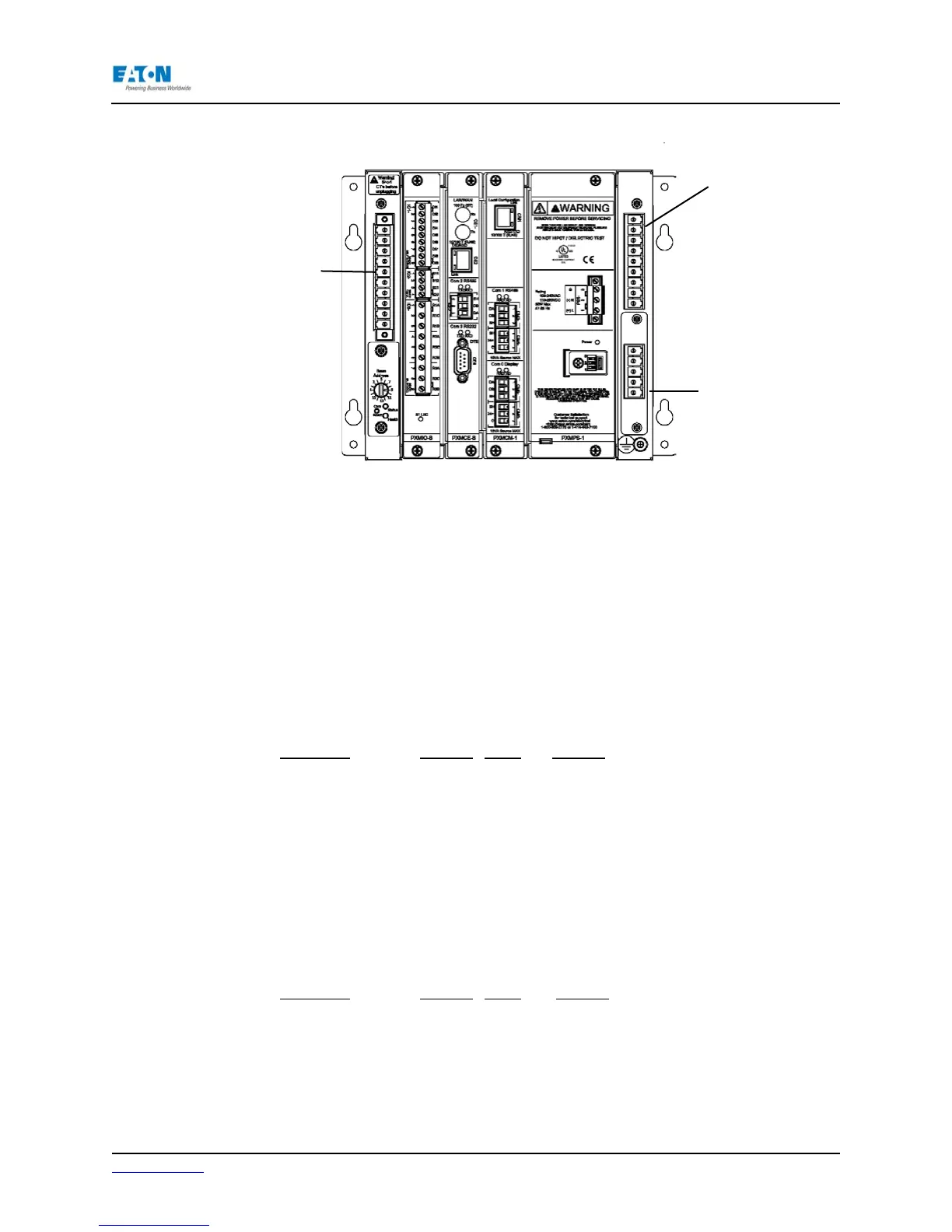
Figure 3: CT & VT Connections
VX Connections
CT Connections
VT Connections
 Loading...