The maximum difference in height with reference to
width and length of the installation shall not exceed 4
mm. Start from the highest location.
1. Position the first section and level it. If the floor is not
level use shims at the corners and in the centre.
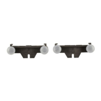
2. Make sure the section is properly and equally
supported. See the illustration for the locations, which
need to be supported.
3. Attach the section at the front side to the floor with
use of M12 bolts. Apply a standard torque 70Nm.
4. Remove the bolts and washers from the coupling rivet
nuts, be careful the side plates keep their position.
5. Move a second section to the first one.
6. Carefully align the side posts of the second section
with those of the first section.
7. Replace the bolts and washers in step 4 and apply a
torque for 40Nm. For front cable access, Long tools
are used to bolt the top rear side of adjacent section
8. Attach the other sections in the same way as given
before.
9. Install the panel type plates on top of the installation,
which corresponds with the panel below.
10. Repeat (3) above for all other panel sections in the
switchgear to align and fix to the level floor.
 Loading...