6 Eaton Tripp Lite Series Cloud Connected UPS Systems User Guide 934859—Rev B
22..33 SSttaannddaarrdd MMoouunnttiinngg IInnssttaallllaattiioonn
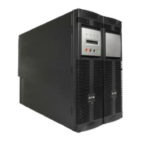
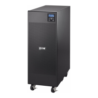
The Tripp Lite Series UPS system can be installed in the following standard mounting orientation.
NOTE Do not install the unit on its sides, front or back. The UPS can become unstable and tip
over, causing damage to the product.
Figure 8. Standard Mounting
22..44 VVEESSAA MMoouunntt IInnssttaallllaattiioonn
The M4 X12 mm VESA screws (provided) may not be compatible with every monitor. Consult the monitor user
manual for screw depth and equipment weight specifications for VESA mount applications.
The UPS has rear keyhole spaces 100 mm apart for optional VESA mounting in a vertical or horizontal position.
To mount:
1. Install the four M4 x12 mm VESA mount screws (provided) in the desired holes in the back of the monitor
leaving the screws extended about 0.28 inches.
2. Center the UPS keyhole openings over the screw heads and push towards the monitor and then down
lightly to lock it onto the screws.
NOTE The arrows on the bottom label of the UPS indicate the correct orientation to observe
when installing the unit. See Figure 6.
3. To detach the UPS from your monitor, lightly push up on the bottom of the UPS to release it from the
monitor.
4. Carefully lift the UPS off the monitor.
Figure 9. VESA Mount Installation
Standard Mounting Installation

 Loading...