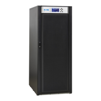
45UPS 20-40 kVA, 230/400 V 50/60 Hz output
User’s Guide
1025358
Revision D
Figure 25 Bypass wiring diagram and cable length notes
Aux. MBS contacts
Position data connection between SPM and UPS should also be done before taking system in
operation. Follow the procedure below to build up position data connection:
1. Remove the door from the UPS.
2. Connect the cables in UPS’s programmable input terminal X44 or X45.
3. Connect communication cables to terminals 1 and 2 for UPS Module #1 and to terminals
3 and 4 for UPS Module #2 in the SPM.
Note!
Signal input cables need to be connected to all UPS when used.
Before proceeding see the Start-up procedure.
4. Start the UPS(s) if not already started.
5. Push any key of the control panel of the UPS to enable the functions on the LCD screed
 Loading...

