This document is an Overhaul Manual for Vickers Vane Pumps, specifically covering Single Stage Single and Double Vane Pumps. The manual, identified as I-3100-S and reprinted on December 1, 1986, provides comprehensive information for the maintenance and repair of these hydraulic components.
Function Description
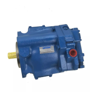
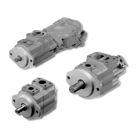
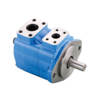
Vickers vane pumps are hydraulically balanced cartridge-type vane pumps designed to provide a constant supply of hydraulic fluid under pressure. They are available in single and double pump configurations, utilizing cartridges of different displacements that can be used interchangeably within each series. The double pump configurations allow for an almost infinite number of combinations by assembling two pump units on a common drive shaft.
The pumping action is performed by cartridges, which consist of a ring, rotor, two bushings, twelve vanes, and a locating pin or screws. A splined pump shaft rotates, driving a slotted rotor. Vanes within the rotor slots are thrown outward by centrifugal force and held against a double-lobed cam ring by system pressure. As the vanes move in and out while following the cam ring, the chambers between them increase in size, drawing fluid from the reservoir through the inlet porting. Conversely, as the vanes cross the outlet porting, the chamber size decreases, forcing fluid into the system. The pump's displacement is determined by the size of the cartridge ring. Certain ring changes, such as the 11 gpm ring in the small series and the 36 gpm ring in the intermediate series, require additional changes to the rotor, vanes, and head due to their use with wider vanes and rotors.
Important Technical Specifications
The pumps are characterized as "Balanced Vane, Fixed Delivery" and are available in "Single and Double, Single Stage" series. Performance data is based on an input speed of 1200 rpm, using petroleum base fluid at 100° F (150 S.S.U.). The minimum recommended drive speed for all series is 600 rpm. Characteristics at other drive speeds are approximately proportional to rpm.
Single Pump Series - Single Stage:
- Small Series (50 lbf. in. head bolt torque):
- Models: V104, V105 (Y, E, G, A, C, D variants)
- Maximum Drive Speed: 1800 rpm (Y, E, G, A), 1500 rpm (C), 1200 rpm (D)
- Delivery (gpm at 1200 rpm, 0 psi): 1.8 to 11.5
- Horsepower Input (at 1200 rpm, 0 psi): 0.20 to 0.40
- Intermediate Series (150 lbf. in. head bolt torque):
- Models: V124, V125, V134, V135 (20, U-20, X-20 variants)
- Maximum Drive Speed: 1500 rpm (V124, V134, V134U), 1200 rpm (V134X)
- Delivery (gpm at 1200 rpm, 0 psi): 15.4 to 29.9
- Horsepower Input (at 1200 rpm, 0 psi): 0.70 to 1.00
- Large Series (150 lbf. in. head bolt torque):
- Models: V144, V145, VF-40, VG-40, V-360, V-361, V-460, V-461
- Maximum Drive Speed: 1200 rpm
- Delivery (gpm at 1200 rpm, 0 psi): 37.9 to 60.6
- Horsepower Input (at 1200 rpm, 0 psi): 1.20 to 2.70
Double Pump Series - Single Stage:
Combinations are detailed for Small Series, Intermediate and Small Series, Large and Small Series, and Large and Intermediate Series. These tables provide delivery (gpm) and horsepower input for both head-end and shaft-end pumps at various pressures (0, 500, 1000 psi). For example, a V-108-YY-10 (Small Volume - Head End Pump) has a delivery of 1.8 gpm at 0 psi, while a VVSF-14-40 (Small Volume - Head End Pump) has a delivery of 15.4 gpm at 0 psi. The Large Volume - Shaft End Pumps in these combinations show deliveries ranging from 1.8 gpm to 60.6 gpm at 0 psi, with corresponding horsepower inputs.
Usage Features
- Mounting: Face, Foot, Flange, Electric Motor End Bell.
- Connections: Pipe Thread Body Ports or Flanges.
- Fluid: 150 S.S.U. at 100° F petroleum base fluid is the standard. Performance data for other fluids requires consulting applicable installation drawings.
- Rotation: Cartridge parts must be installed correctly for the desired direction of shaft rotation (right hand or left hand), as viewed from the shaft end. A stepped diameter locating pin (or screw for large series) ensures proper assembly.
- Head Screw Adjustment: Head screws should be tightened gradually and alternately (180° apart) until the head seats evenly on the bushing. The shaft should be turned by hand during this process until a light, smooth snugness is felt. Over-tightening can cause the shaft to bind.
- Starting: A new or overhauled pump must be started under load on the first run to create back pressure for adequate internal lubrication. After break-in, "no-load" conditions are permissible. The pump should be "jogged" a few times to ensure priming.
- Shaft Alignment: Proper shaft alignment with the drive motor is crucial, and a flexible coupling must be used to accommodate minor misalignments.
- Side Loading: Care must be taken to prevent excessive side loading of the drive shaft when using belts, chain drives, or spur gears.
- Pressure Limits: A relief valve is necessary to limit maximum system pressure to recommended ratings, as operation beyond these limits will shorten pump life.
Maintenance Features
- Overhaul: Complete overhaul can be performed using cartridge and gasket kits.
- Routine Inspection and Maintenance:
- Hydraulic Connections: Ensure all connections are tight to prevent fluid leakage or air entry.
- Fluid Level: Maintain adequate fluid level in the reservoir. When adding fluid, always pour it through a 200 mesh or finer screen.
- Filter Element: Inspect and replace if dirty.
- Fluid Contamination: If contaminated, drain, clean, and flush the entire system, then refill with new fluid. Change filters as needed.
- Reservoir Air Breather: Inspect and replace if dirty.
- Disassembly and Reassembly:
- Safety: Before breaking circuit connections, ensure power is off, system pressure is released, and all loads are secured.
- Cleanliness: Work on a clean, lint-free surface. Cap or cover all exposed ports and openings to prevent dirt entry.
- Inspection and Replacement:
- Vanes: Inspect for wear and sticking. Replace if defective. Stone new vanes lightly to remove sharp edges.
- Ring: Inspect for scored or cross-grooved cam face. Replace if grooved or scored.
- Rotor and Bushings: Inspect faces for wear and scoring. Light scores can be removed by lapping; heavy scores require replacement. Stone new parts lightly to remove burrs.
- Bearings: Inspect for cracked or pitted races or balls. Replace if defective.
- Shaft: Inspect for wear at the seal lip journal. Replace if scored.
- Seals: Replace shaft seal, O-ring, and head packing at each teardown.
- Reassembly Notes: Assemble seals with the spring toward the inside of the pump. Coat all parts with compatible fluid and lightly lubricate the shaft seal lip to prevent damage during installation. Install bearing and snap ring on the shaft end before placing it in the body.
- Troubleshooting: A detailed troubleshooting chart is provided to diagnose common issues such as "Pump not delivering fluid" and "Pump making noise," listing probable causes and remedies. Causes include wrong direction of rotation, broken drive shaft, clogged intake, air leaks, low oil level, stuck vanes, defective bearings, and coupling misalignment.
- Lubrication: Current design models do not require lubrication. Older designs with a grease fitting on the pump body (and sometimes a relief fitting on the bottom) should be lubricated sparingly (approx. one tablespoonful every six months) with a good quality, high-temperature bearing grease. Over-lubrication can damage the shaft seal.