65A7355H01 November 2011 www.eaton.com
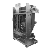
4.6 Main Circuit Resistance Check
The resistance of the main circuit can be measured as
follows: Ensure the breaker is in closed status, deliver
100A DC current to the main circuit, and measure the
DC resistance with the help of a test machine. The
results cannot exceed the value in the Table 4-2. When
conducting this test with a withdrawable breaker, DO
NOT attach the test clamp to the springs. Use Fig. 4-1
as reference.
Table 4-2: Resistance chart of Main Circuit
When testing circuit resistance: DO NOT directly
clamp onto the springs when injecting current.
When testing circuit resistance: clamp directly onto
the finger cluster between the springs as shown.
Fig. 4-1: Finger Cluster Warning
Mechanism Inspection Check
Carefully inspect the mechanism for any possible loose
parts such as bolts, nuts, pins and rings. Check for
excessive wear or damage to the breaker components.
Operate the breaker several times manually and
electrically. Check the closing and opening times to
verify that they are in accordance with acceptable
limits. Refer to the technical parameters sections 2.4,
2.5 and 2.6 for closing and opening time limits.
4.7 Torque specifications
Table 4-3: Torque Specifications
 Loading...