Snap the “Temperature sensor cable loom” cables into the 2-pin
connector (small parts bag) as shown.
Plug the connector into the 2-pin slot (2nd from left) of the station-
ary unit.
Æ
EasyStart Web receiver unit, 2-pin slot
1 BNWH cable
2 GY cable
3.4 Connect the cable loom (heaters with LIN-/ S+
interface)
Standard configuration
3.4.1 Connect the communication and power supply cables
Check whether the receptacles are available on the RD, BN and
BUWH cables in the “Operation” lead harness of the heater cable
loom.
If the receptacles are missing on the relevant cables or incorrect
receptacles are installed, crimp on the sleeves from the small parts
bag supplied.
Snap the cables into the 5-pin receptacle housing as follows.
– rt cable in chamber 1
– br cable in chamber 3
– BUWH cable in chamber 4
Connect the 5-pin receptacle housing of the “Operation” lead
harness to the 5-pin “cable loom” connector.
For air heaters, connect and insulate the GYRD cable to the BNWH
also.
Insulate unused cables.
Connect the two 4-pin connectors of the “cable loom” in the corre-
sponding slots of the EasyStart Web receiver unit (flat 4-pin –> far
left, square 4-pin –> far right)
6
1 “Operation” lead harness
2 Receptacle housing, 5 pin
3 “Cable loom” connector, 5 pin
4 Flat (tab) connector, 4 pin
5 Square connector, 4 pin
6 EasyStart Web receiver unit
Note
Note and follow the circuit diagrams from page 16.
Cable colours
RD red GR grey BK black WH white VT violet
BU blue YE yellow GN green OR orange BN brown
3.5 Connect the cable loom (heaters with CAN
interface)
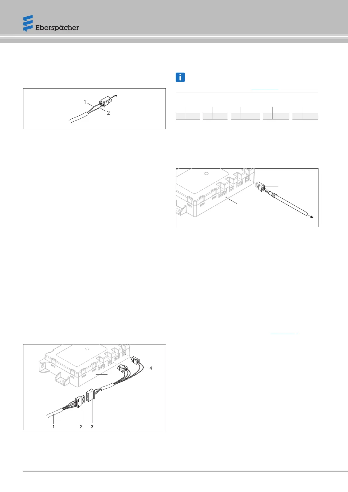
Connect 4-pin connector housing -XS1 from heater lead harness in
the right-hand slot of the EasyStart Web module.
1
3
2
1 Square connector, 4 pin
2 to the heater lead harness
3 EasyStart Web receiver unit
3.6 Connecting the power supply
After installing the heater and EasyStart Web receiver unit, push in
the fuse to establish the power supply for both units.
3.7 Automatic detection
After applying the operating voltage the button's LED starts to light
up. EasyStart Web checks which heater is connected and configures
the system accordingly.
Start the initial startup and configuration (see from page 9) of
EasyStart Web when the LED in the button is no longer flashing.
8 22.1000.34.5106.0D EN | 06.2019
Operating instructions | EasyStart Web
 Loading...