EBTRON • 1663 Hwy. 701 S., Loris SC 29569 • Toll Free: 800.2EBTRON (232.8766) • Fax: 843.756.1838 • Internet: EBTRON.com 17
GOLD SERIES GTC116 TRANSMITTER
a measurable difference!
EBTRON
IG_GTC116_R3A
5.8 ViewingSensorData
5.8.1 ViewingSensorDataontheLocalLCDDisplay
Airflowand temperatureofindividualsensorscanbe displayed on the local LCD displayby enteringthe
DiagnosticMenu.Simultaneouslydepressthe up↑ and down↓ arrowsto entertheGTC116 SETUPmenu,and
thennavigateto the Diagnosticsubmenu.
5.8.2 ViewingSensorDataviaBACnet,ModbusnetworksorviaEB‐LinkReader
AirflowandtemperatureofindividualsensorscanbereadacrossBACnetor Modbusnetworks,ordownloaded
directlyto an EB‐ Link Reader if the infra‐redEB‐Linkoption hasbeeninstalled.Refertothe followingSensor
AddressingandProbePositioningparagraphforthesuggestedprobeinstallationconfiguration.Tables2and
3
provideBACnetobjectsandregisteraddressinginformationforindividualsensordata.
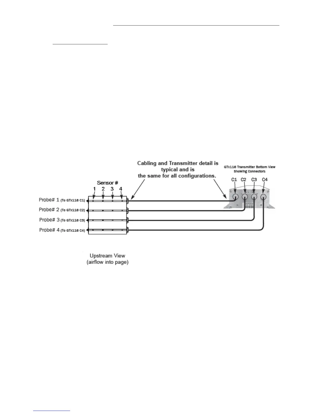
5.8.3 SensorAddressingandProbePositioning
Sensorsareautomaticallyaddressedafterpowerisappliedtothetransmitterasfollows:
Theprobeconnectedtotheleftmostconnector,C1,isdefinedasprobe1.Thesensoroppositethecableendof
theprobeisdefinedassensor1whenviewingindividualsensordata.RefertoFigure7below
foradditionaldetail.
Notethatifonlyaveragedataisdesired,themountingpositionoftheprobesisnotcritical. Whenaprobeis
disconnectedandthenpluggedintoadifferentport,thetransmitterwillre‐discoveritwithin15secondsand
makeanynecessaryaddressingadjustments.
Tostandardizeinstallationand
decodingofdata,particularlywhenusingtheEB‐LinkReaderproduct,EBTRON
recommendsalefttoright(ortoptobottominverticalapplications)sensorprobemountingconventionas
detailedintheseparatesensorprobeinstallationinstructions.
6 SETUPMENUS
AppendixAdetailsthevarioussetupmenusandsubmenus.
7 WIRINGDIAGRAM
AppendixBisthewiringdiagramfortheGTC116transmitter.
Figure7.SensorAddressingandProbePositioningDetail
 Loading...