8 EBTRON • 1663 Hwy. 701 S., Loris SC 29569 • Toll Free: 800.2EBTRON (232.8766) • Fax: 843.756.1838 • Internet: EBTRON.com
GOLD SERIES GTC116 TRANSMITTER
a measurable difference!
EBTRON
IG_GTC116_R3A
4 GTC116ANALOGOUTPUTANDNETWORKCONNECTIONS
ThissectioncontainsanalogandnetworkoutputwiringinstructionsfortheGTC116transmitterwithRS‐485and
DualAnalogoutputs.
4.1 GTC116‐ANALOGOUTPUTWIRING
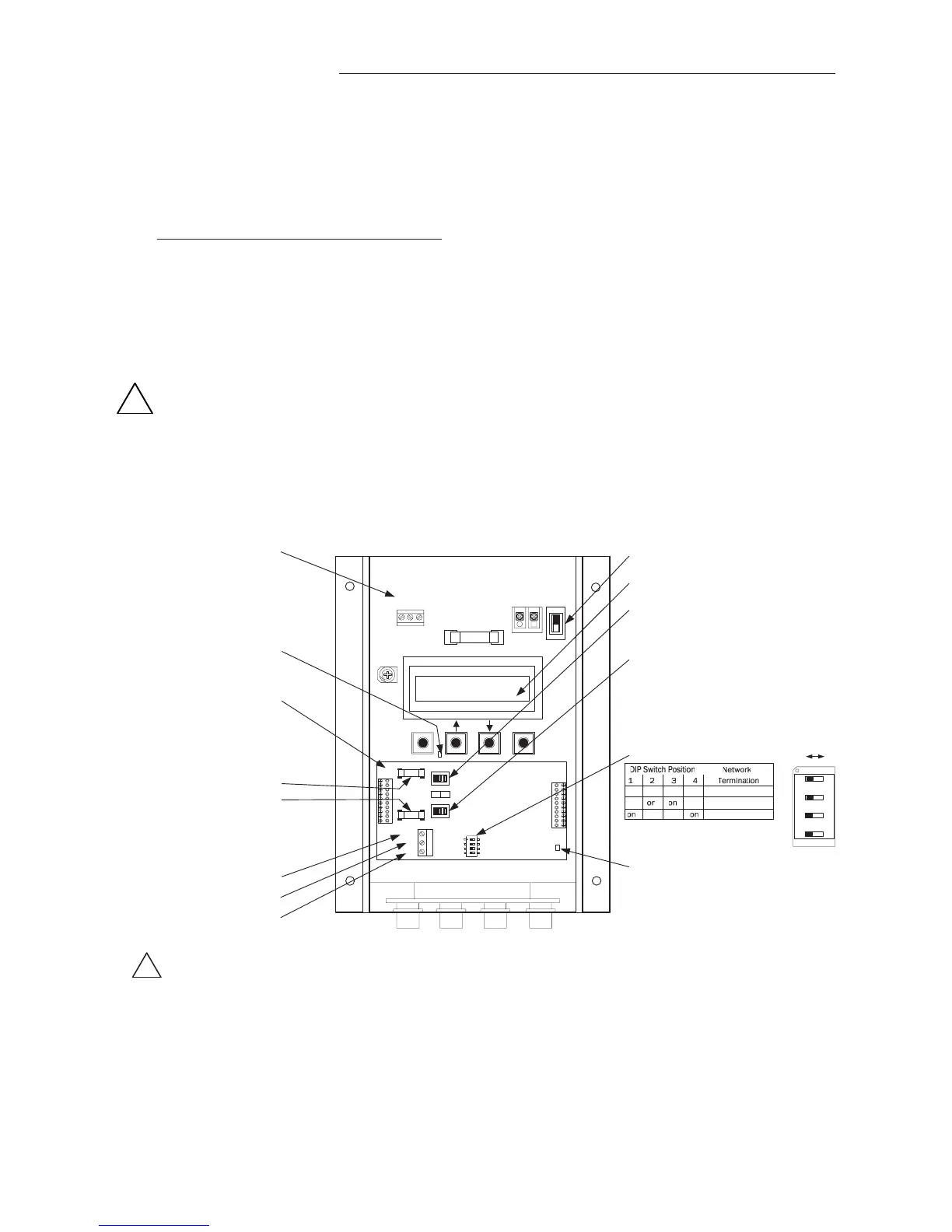
AnalogoutputconnectionsaremadeatthetopleftofthetransmittermaincircuitboardOUTPUTconnectoras
showninFigure6.IndependentlinearanalogoutputsareprovidedforairflowatOUTPUTterminal1,andfor
temperature(oralarm)atOUTPUTterminal2,eachwithovervoltageandovercurrentprotection.
Airflowand
temperatureoutputsarefieldselectableforeither0‐5/0‐10VDCor4‐20mA.TheOUTPUTterminal2canbe
assignedasanAlarmoutputtoprovideanactivehigh,activelowortroublealarmoutput.Outputsaregalvanically
isolatedfromthemainpowersupplytopermitsimple
integrationwithvirtuallyallbuildingautomationsystems.
Whenconfiguredfor4‐20mAoutput,theGTC116isa“4‐wire”device.Thehostcontrolsshallnotprovide
anyexcitationvoltagetotheoutputoftheGTC116.
Fortheanalogoutputs,shieldedcableisrecommended.Towiretheanalogoutputs,slidethecoverplateupand
offoftheenclosure.Ensurethatthepowerswitchisinthe“OFF”position.Connectsignalwiresforairflowrate
andtemperature(oralarm)tothesmall,threepositionoutputterminallabeled
“OUTPUT”ontheupperlefthand
sideofthemaincircuitboardasshowninFigure6.
Figure6.GTC116CombinationAnalog/RS‐485TransmitterInteriorDetail
ON
OFF
OFF ON
ESC ENTER
CONTRAST
REPLACE WITH
1.5 AMP
FAST ACTING ONLY
OUTPUT
1 2 COM
POWER
24VAC IN
L2 L1
ON
OFF
RS-485
NET COM
NET -
NET +
ON
TERM
F1
F2
VDC mA
OUT 1
OUT 2
RS-485
ANALOG OUTPUT
1: Airflow
2: Temperature/Alarm
COM: Common
(RS-485 output below)
Transmitter Status LED
(Green 1 second flash normal;
2 second flash for trouble)
Combination Analog/
RS-485 Output Card
P.N. 800-1825
Analog Output Fuses
F1=OUT1
F2=OUT2
UL Listed 0.125 Amp
P.N. 800-1105 (Qty:10)
NET COM*
NET -
.
NET +
RS-485
OUTPUT
(For Analog Output, see
separate output above)
Power Switch
LCD Display
SW1 (for OUT1)
Airflow Output Signal Select
SW2 (for OUT2)
Temp./Alarm/Trouble Output
Signal Select
VDC: 0-5/0-10VDC or
mA: 4-20 mA
RS-485 Activity LED
(Green LED indicating RS-485 network activity)
*CAUTION
The common for the ANALOG and the RS-485 outputs must be at the same potential.
For ISOLATED RS-485 output, COM connection MUST BE CONNECTED to network common.
For NON-ISOLATED output, COM connection MUST BE CONNECTED to the common ground that other network devices are using (typically the
ground side of the 24VAC supply - L2 of the POWER terminals). Refer to RS-485 Network Wiring Connections paragraph for additional detail.
off off off off No Termination
off
off End of Line
off off Fail-safe Bias
!
!
SW3 TERMINATION Switch