18 EBTRON • 1663 Hwy. 701 S., Loris SC 29569 • Toll Free: 800.2EBTRON (232.8766) • Fax: 843.756.1838 • Internet: EBTRON.com
GOLD SERIES GTC116 TRANSMITTER
a measurable difference!
EBTRON
IG_GTC116_R3A
APPENDIXA‐
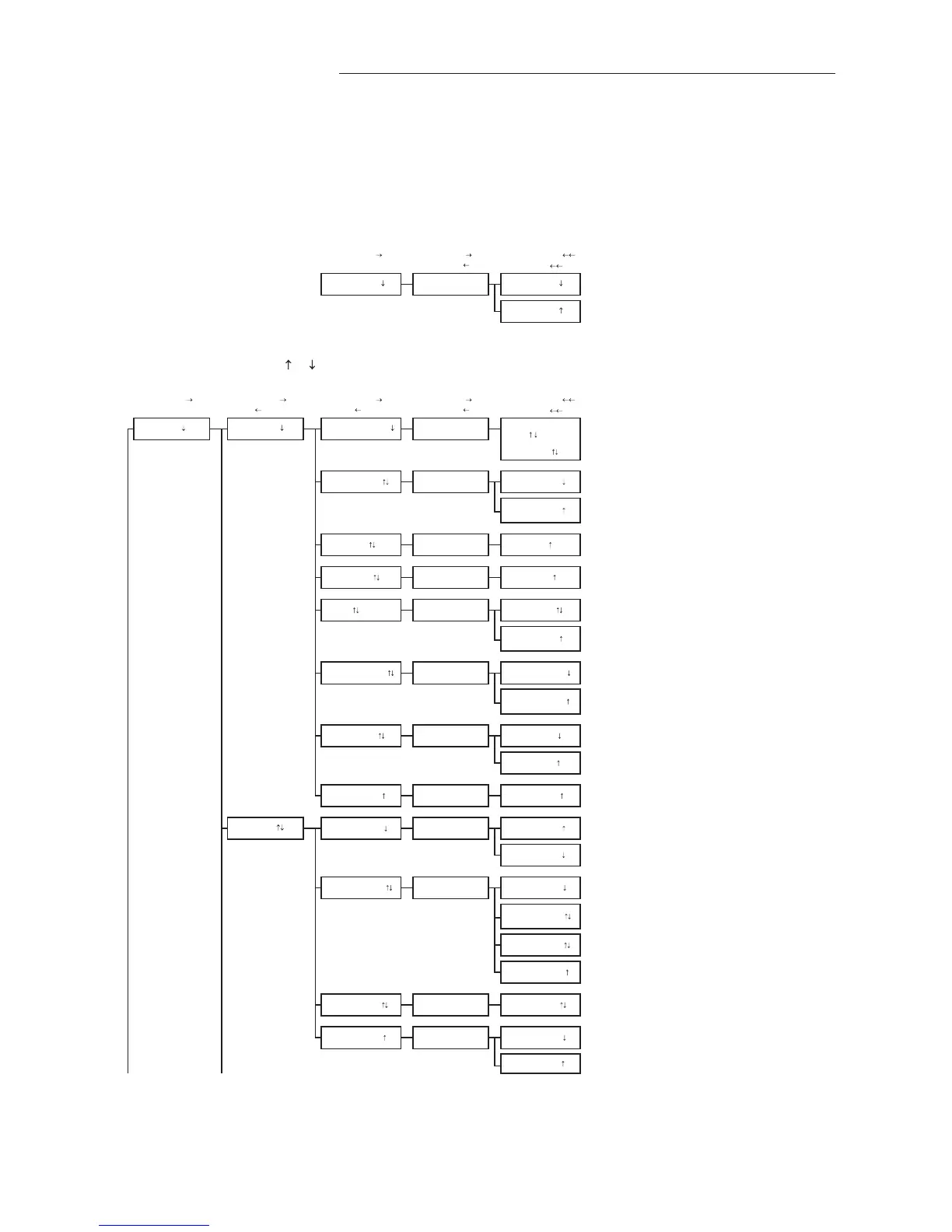
ADVANTAGE3‐ SETUPMENUS
SYSTEM OF UNITS MENU
Simultaneously depress/release ENTER + ESC keys during normal operation to select
* Factory Default/Current Setting
Enter (move
) Enter (move ) Enter (action, move )
Esc (normal oper.)
Esc (move
)
Esc (move
)
ACTION
SETUP MENU
Simultaneously depress/release
+ keys during normal operation to select
* Factory Default/Current Setting
Enter (move
) Enter (move ) Enter (move ) Enter (move ) Enter (action, move )
Esc (normal oper.)
Esc (move
or prev setting) Esc (move or prev setting) Esc (move )
Esc (move
)
ACTION
Only when AIRFLOW=ACT
TO PART 5 'A' TO PART 2
AUTO forces a re-read of the one-wire value. (AUTO not available if area value has not been
written into one-wire chip).
Integration samples for LCD.
SET LCD DSPL? LCD DSPL=OFF
LCD DSPL=FLOW
Set what is displayed on LCD.
LCD DSPL=BOTH
*LCD DSPL=BOTH
LCD UM=AFPM
*LCD INTG=100 SET LCD INTG? LCD INTG=100
GENERAL *NAME={unit serial#}
SET NAME ?
*LCD TRBL=ON
SET LCD TRBL? LCD TRBL=OFF
ON FAIL=HI
*EXT CABLE=0 SET EXT CABLE? EXT CABLE=0
SETUP
*AIRFLOW=ACT SET AIRFLOW?
AIRFLOW=STD
SET ALT?
Set the airflow measurement to ACTUAL units (AFPM/ACFM)
Set the airflow measurement to Standard units (SFPM/SCFM)
AIRFLOW=ACT
Custom LCD Flow Text: Blinking prompt at position of the selected character. Character is
selected using the up and down arrows and then ENTER to accept and move cursor forward
(right); ESC moves the cursor back (left). Use space characters
for blank or unwanted text.
Instruction text:
"USE
AND ENT"
then:
NAME= _
IP/SI=IP SYS
*LCD UM=ACFM
IP/SI=SI SYS
*LLIMIT=0
DISPLAY
ALT=0
*ON FAIL=LO SET ON FAIL?
*ALT=0
Set LCD airflow display units to CFM or FPM. (Note: A-ACT or
S-STD measurement prefix is set by AIRFLOW= setting above).
This is always a velocity value.
*AREA=
{from setup}
*TEMP METH=WGT
SET IP/SI ?
AREA=xx.xx
*IP/SI=IP SYS
SET AREA?
ON FAIL=LO
Set system of units to I-P (FPM, CFM, sq.ft., ºF)
or Set system of units to S.I. (MPS, LPS, sq.M., ºC).
NOTE:
Changing IP/SI SYS resets alarm settings and scaling values.
Set the altitude above sea level for flow correction: 0 to 18,000 ft.
LLIMIT=0
SET LCD UM? LCD UM=ACFM
SET TEMP METH?
SET LLIMIT?
AREA=AUTO
Enter length of extension cable.
Note: Value is from one-wire but can be overridden.
Set whether or not TROUBLE will display on LCD during a trouble condition.
TEMP METH=WGT
Set temperature output for velocity weighted average of temperature sensors.
TEMP METH=AVG
Set temperature output for mathematical average of temperature sensors.
Sets transmitter analog output state in the event of a major fault (all sensor failure) expressed
as HI for full scale analog output or LO as minimum scale analog output.
LCD DSPL=TEMP
LCD TRBL=ON
 Loading...