IGNITION SYSTEM
CS-271T
16
3-4 Inspectingignitionswitch
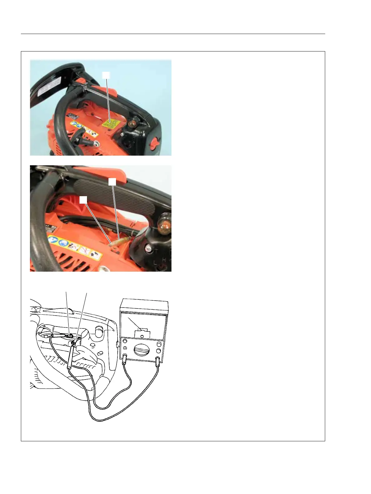
1. Remove dust cover (A).
2. Disconnect ignition switch terminal (B) from pri-
mary lead terminal (C).
3. Connect one probe of Ohm-meter or multi-meter
to ignition switch terminal (B). Connect the other
probe to another ignition switch terminal (D).
4. When ignition switch is upward (“RUN” position),
tester should indicate innite resistance.
5. When ignition switch is in “STOP” position, tes-
ter should show that the circuit is in conducting
state (closed circuit).
6. If ignition switch is defective, replace with a new
one.
B
A
D
B
C