7
STARTER SYSTEM
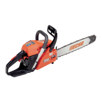
CS-370ES
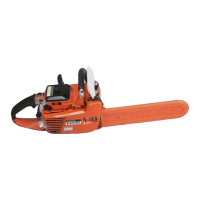
CS-420ES
Working principle
1. When starter grip is pulled, rope reel (D) rotates.
2. The rotation force of rope reel (D) is transmitted
to pawl catcher (F) by power spring (E) that is
connected with rope reel (D) and pawl catcher (F).
3. Pawl catcher (F) engages with starter pawls on
flywheel to turn crankshaft.
4. The load from compression pressure in cylinder
will keep crankshaft from rotating as power spring
(E) is twisted and accumulates energy.
5. Starter grip is pulled further; more energy is
stored in power spring (E) until the accumulated
energy is enough to overcome the compression
pressure in cylinder.
6. When accumulated energy in power spring (E)
overcomes the load from compression pressure in
cylinder, crankshaft will be rotated.
7. Power spring absorbs compression resistance of
cylinder and snatch back of engine during starting
action.
8. When starter rope is released, rope reel (D) is
returned together with power spring (E) and pawl
catcher (F) by rewind spring tension.
9. After engine starts, starter pawls pivot outward by
centrifugal force and disengage from pawl catcher
(F).
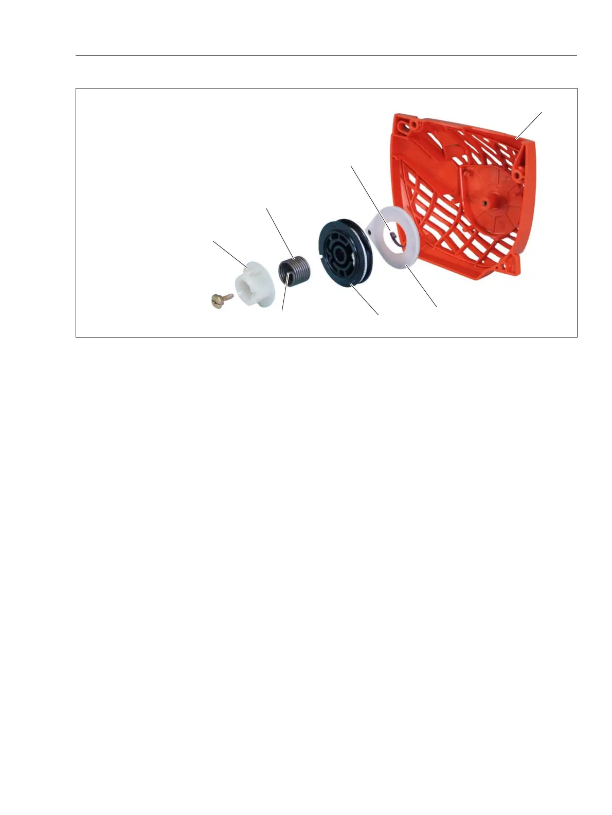
2 STARTER SYSTEM (ES starter)
(A) Starter case
(B) Rewind spring
(C) Rewind spring case assembly
(D) Rope reel
(E) Power Spring
(e) Hook end of power spring
(F) Pawl catcher
F
E
A
D
C
B
e
Construction
1. Rewind spring case assembly (C) is installed
inside starter case (A).
2. Rope reel (D) with starter rope is installed on
rewind spring case assembly.
3. Hook located on the backside of rope reel
engages with end of rewind spring (B).
4. Power spring (E) is installed on rope reel.
5. Hook of power spring engages with rope reel and
top end hook (e) of power spring engages with pawl
catcher (F).