Eclipse ThermAir T/A Series v1.10, Installation Guide No. 114, 4/7/06
22
Step 2: Verify the system
Note:
A pressure tap is open when the screw inside the tap is
Note:
Chamber pressure will directly influence air flow from the
blower. Air flows should be rechecked once the process reaches
its operating temperature and pressure. An oxygen analyzer
may be used to confirm air flow rates once the system is
Step 3a: Ignite the burner
(Option 1: Burner not
equipped with bypass start
gas.) Ref. illustration page 21.
Warning:
This procedure assumes that a flame monitoring
control system is installed and is serviceable. It
also assumes that normal low fire start is being
used.
If low fire gas is too low to be used for ignition
consider increasing low fire or providing bypass
There are two separate ignition procedures which depend upon
whether or not bypass start gas is installed on the burner. Each
procedure is unique and both are outlined below.
1. Drive the gas control valve to low fire.
Note:
All ThermAir burners are limited to ignition at inputs below
40% of maximum unless the control circuit on page 15 of
Design Guide 114 is followed
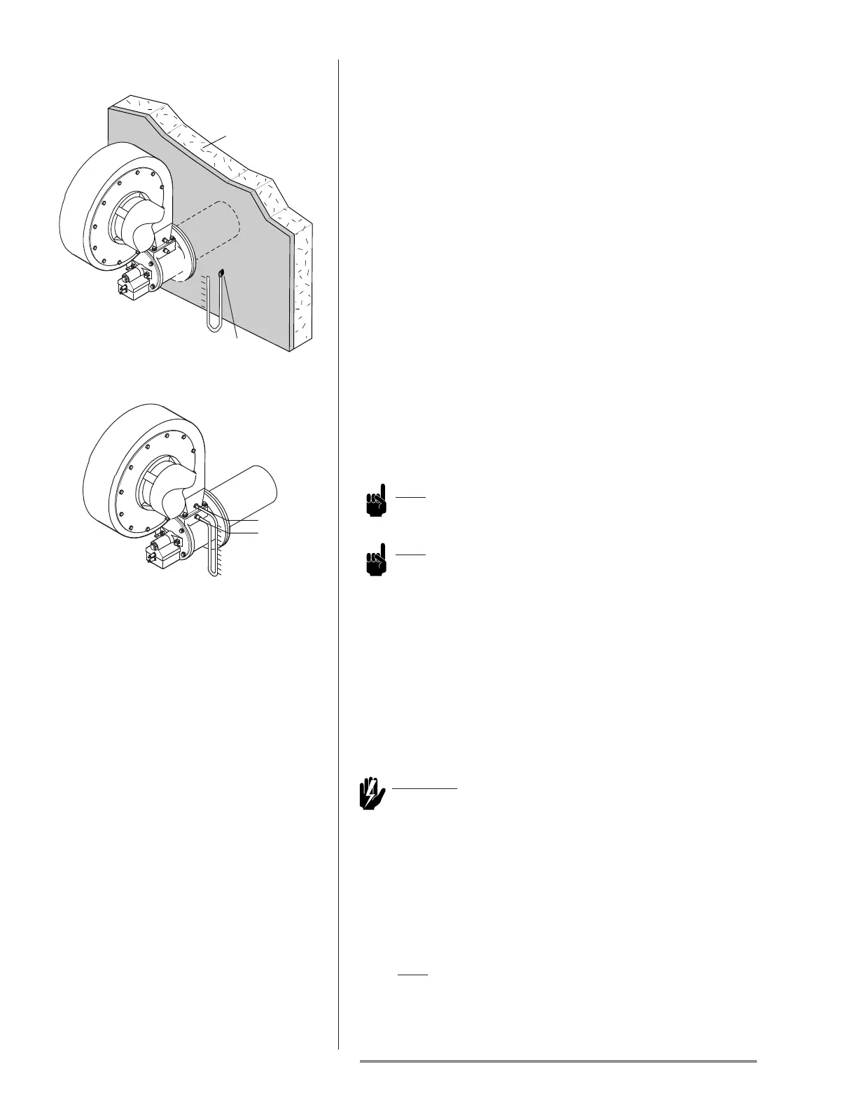
Chamber
Pressure
Tap
Chamber
Wall
TA 015 thru TA 200
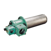
TA 300 thru TA 500
TA 015, 025, 040, 075, 100, 200
1. Make sure that the pressure tap located on the chamber is
open.
2. Connect the manometer to the chamber pressure tap.
3. Measure the chamber air pressure.
4. Determine actual air flow from the burner specific Data
Sheet (ref.: Air flow vs. Chamber Pressure Chart) for the
burner being setup.
5. Remove the manometer.
6. Close the pressure tap.
1. Make sure that pressure taps A and C are open.
2. Connect the manometer to taps A and C.
3. Measure the air differential pressure.
4. Determine actual air flow from the burner specific Data
Sheet (ref.: Air flow vs. Air Orifice ∆P Chart) for the burner
being setup.
5. Remove the manometer.
6. Close the pressure taps
TA 300, 400, 500