pag.11
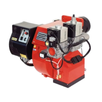
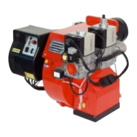
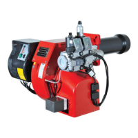
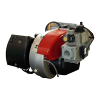
LB 447 Blu 500 ÷ 700 P B
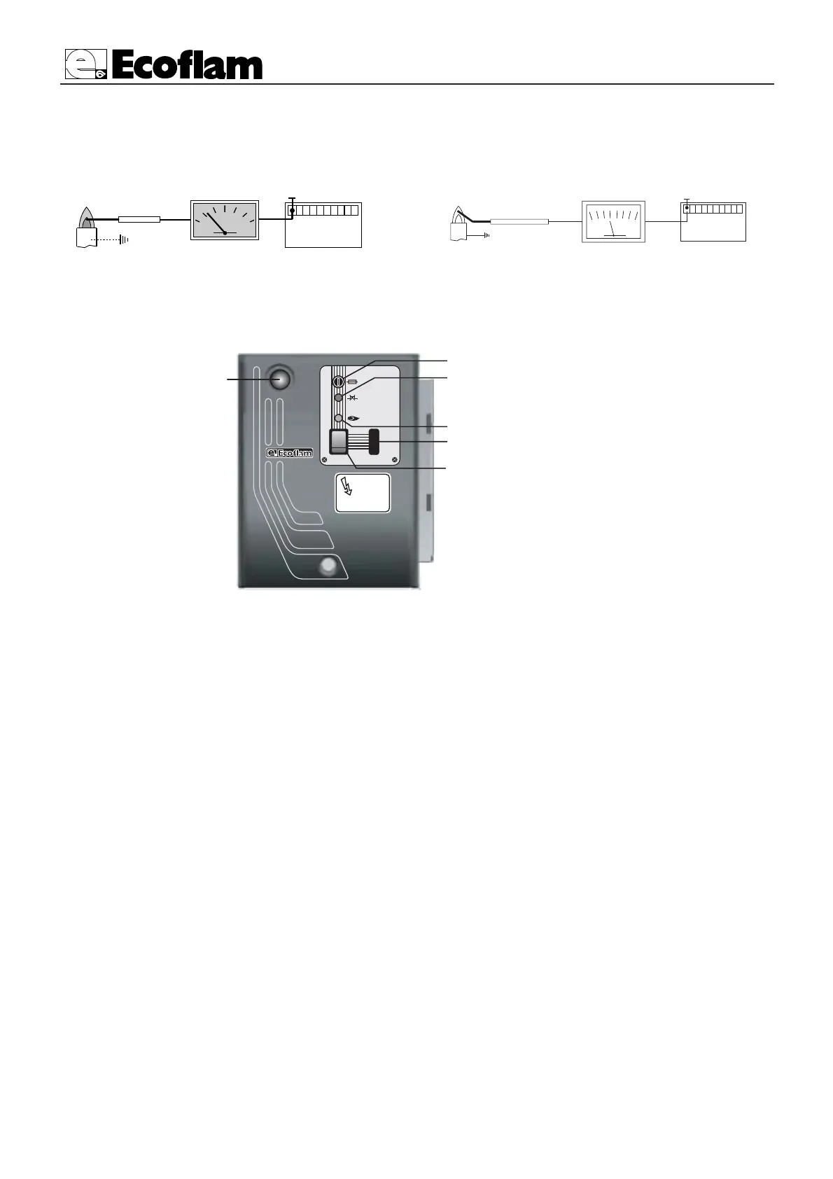
DESCRIPTION OF THE CONTROL PANEL OF THE BURNER
YEARLY INSPECTION : Periodic inspection of the burner (combustion head, electrodes, etc.) must be carried out by
authorised personnel once or twice a year, depending of use. Before carrying out maintenance inspection on the burner,
it is advisable to check its general condition and carry out the following operations: - Disconnect the burner from the
power supply (remove the plug). - Close the gas cock. - Remove the burner cover, clean the fan and air intake. -
Clean the combustion head and check the position of the electrodes. - Re-assemble the parts. - Check the seal on the
gas pipe fittings. - Check the flue. - Restart the burner. - Check the combustion parameters (CO
2
= 9.5 to
9.8),(O = less than 75 ppm).
BEFORE EACH INTERVENTION CHECK; - That the system is supplied with power and the burner connected.
- That the gas pressure is correct and the gas cock open. - That the control systems are correctly connected.
If all these conditions are present, start the burner by pressing the release button. Check the burner cycle.
THE BURNER WILL NOT START; - Check the switch, thermostats, motor, gas pressure.
THE BURNER PREVENTILATES AND LOCKS AT THE END OF THE CYCLE:
- Check the air pressure and fan. - Check the air pressure switch.
THE BURNER PREVENTILATES AND WILL NOT IGNITE: - Check the assembly and position of electrodes.
- Check the ignition cable. - Check the ignition transformer. - Check the safety devices.
THE BURNER STARTS UP AND LOCKS AFTER THE SAFETY TIME LIMIT: - Check that the phase and neu-
tral wires are correctly connected. - Check the gas electrovalves. - Check the position of the detection electrode and its
connection. - Check the detection electrode. - Check the safety devices.
THE BURNER STARTS UP AND LOCKS AFTER RUNNING FOR A FEW MINUTES. - Check the pressure
regulator and the gas filter. - Check the gas pressure with an ammeter. - Check the detection value (min 1,5-3 µA).
MAINTENANCE
LGB21-LGB22 min. 3 µA
LMG21-LMG22 min. 2 µA
FLAME DETECTION SYSTEM CHECK
With the burner switched off, connect a DC microammeter with a 0÷50 or 0÷100 µA dial. When the burner is run-
ning, and is properly adjusted, the value read must be steady and never be smaller than 1,5/3 µA.
min. 1,5 µA
 Loading...