10
420010280903 Max 15 - 20 - 30
EN
VERIFY:
- That piping system is perfectly sealed.
- That the use of hoses is avoided whenever is possible (use copper pipes preferably).
- That depression is not greater than 0,45 bar, to avoid pump’s cavitation.
- That check valve is suitably designed for the duty.
The pump pressure is set at a value of 12 bar during the testing of burners. Before starting the burner, bleed
the air in the pump through the gauge port. Fill the piping with light-oil to facilitate the pump priming. Start
the burner and check the pump feeding pressure. In case the pump priming does not take place during the
first prepurging, with a consequent, subsequent lock-out of the burner, rearm the burner’s lock-out to restart,
by pushing the button on the control box. If, after a successful pump priming, the burner locks-out after the
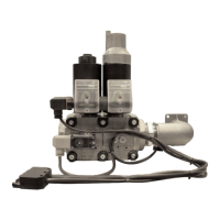
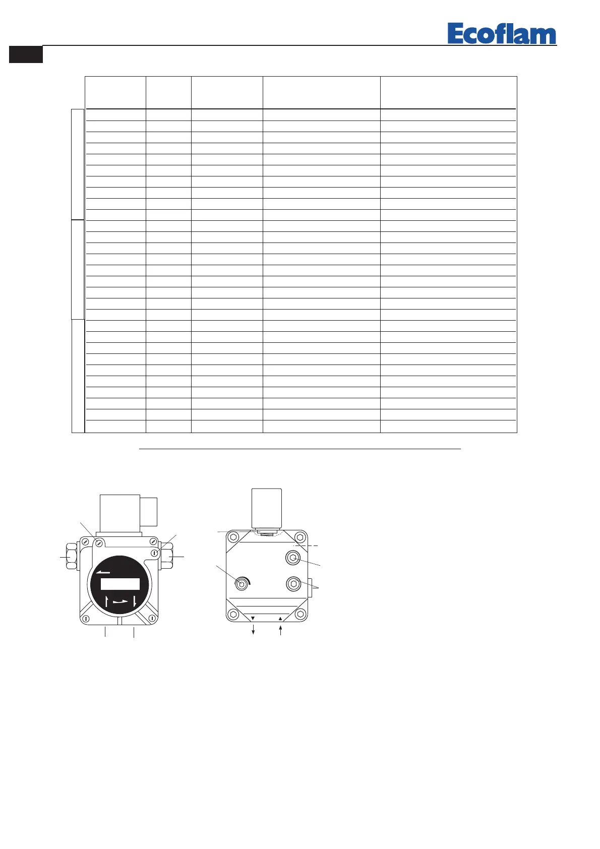
DANFOSS
BFP 21 R3
ADJUSTMENT DATA
NOZZLE : DANFOSS H÷S 80°÷60°; DELAVAN W 60°; STEINEN S 60°
NOZZLE PUMP OUTPUT FIRING HEAD SETTING AIR DAMPER ADJUSTMENT
gph spry bar kg/h Pos. Pos.
1,50 60° 12 6,2 0 1,5
1,65 60° 12 7,0 1 2,0
1,75 60° 12 7,6 2 2,5
2,00 60° 12 8,3 2,5 3,0
2,25 60° 12 9,3 3 3,2
2,50 60° 12 10,4 3,5 3,5
2,75 60° 12 11,5 4 4
3,00 60° 12 12,5 4,5 4,5
3,50 60° 12 14,9 5 4,5
4,00 60° 11 16,0 5 5
1,75 60° 12 7,6 0 1,5
2,00 60° 12 8,3 1 1,7
2,25 60° 12 9,3 2 2
2,50 60° 12 10,4 2,5 2,8
2,75 60° 12 11,5 3 3
3,00 60° 12 12,5 3,5 3,6
3,50 60° 12 14,9 4,0 4,1
4,00 60° 12 16,7 4,5 4,3
4,50 60° 12 19,1 5 5
2,25 60° 12 9,3 0 1,5
2,50 60° 12 10,4 0,5 2
3,00 60° 12 12,5 1,5 2,2
3,50 60° 12 14,9 2,0 2,5
4,00 60° 12 16,7 2,5 3
4,50 60° 12 19,1 3 3,3
5,00 60° 12 21,8 3,5 3,8
5,50 60° 12 23,6 4 4
6,00 60° 12 25 4,5 4,5
6,50 60° 11 27 5 5
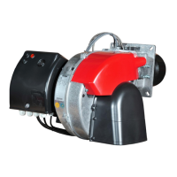
MAX 15
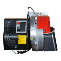
MAX 30
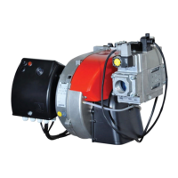
MAX 20
 Loading...