2|
or heat dissipation system are not blocked when the equipment is under
operation.
3. Do not expose the equipment to flammable or explosive gas or smoke. Do
not perform any operation on the equipment in such environments.
4. Do not place the equipment next to any heat source, fire source, or water
source, and not to perform any operation on the equipment next to that
heat source, fire source, or water source.
EQUIPMENT AND PERSONNEL SAFETY
REQUIREMENTS
MOVING THE EQUIPMENT
1. When moving the equipment by hand, wear protective gloves to prevent
injuries.
2. Move the equipment with precaution as it is heavy. When two or more
people are needed to assist in moving the equipment, please ensure
communication and coordination between personnels to prevent being
crushed or sprained.
USING TOOLS
1. Use wooden or fiberglass ladders when you need to perform live working
at heights.
2. Before using a ladder, check that it is intact and confirm its load bearing
capacity. Do not overload it.
3. Make sure the operator is regulated in the use of installation tools, such as
ladders, electric paddles, drills, etc. Make sure the tool power cord is not
tangled.
4. When installing, strictly prevent screws, nuts and spacers from falling
inside the equipment and ensure that the tools (such as electric drill bit)
do not fall into the gap between the installed equipment and the wall to
prevent delaying the installation.
DRILLING HOLES
1. Wear goggles and protective gloves when drilling holes.
2. When drilling holes, protect the equipment from shavings or dust. After
drilling, clean up any shavings or dust that have accumulated at the instal-
lation site in a timely manner, otherwise, it may block the drilled hole.
GROUNDING CONDUCTOR MONITORING
The inverter is equipped with a grounding conductor monitoring device.
This grounding conductor monitoring device detects when there is no
grounding conductor connected and disconnects the inverter from the
utility grid if this is the case. Depending on the installation site and grid
configuration, it may be advisable to disable the grounding conductor mon-
itoring. This can be necessary, if there is no neutral conductor present and
you intend to install the inverter between two line conductors.
1. Grounding conductor monitoring must be disabled after initial start-up
depending on the grid configuration. Safety in accordance with IEC 62109
when the grounding conductor monitoring is deactivated. In order to guar-
antee safety in accordance with IEC 62109 when the grounding conductor
monitoring is deactivated, you have to connect an additional grounding
conductor to the inverter.
2. Connect an additional grounding conductor that has an cross-section of at
least 10 mm
2
. Ground the PE hole of GRID connector and the equipment
enclosure.
DISPOSAL
This marking indicates that this product should not be disposed of with
other household waste within the EU. Recycle this product properly to
prevent possible damage to the environment or a risk to human health via
uncontrolled waste disposal and in order to promote the sustainable reuse
of material resources. Please return your used product to an appropriate
collection point or contact the retailer where you purchased this product.
Your retailer will accept used products and return them to an environmen-
tally-sound recycling facility.
For information on the disposal of electrical and electronic equipment,
please refer to the following website:
https://eu.ecoflow.com/pages/electronic-devices-disposal
SETTING THE RATED RESIDUAL CURRENT OF THE
RESIDUAL-CURRENT DEVICE
RCDs (Type A) with a rated residual operating current are recommended to
install, 300mA on the AC-GRID side, and 30mA on the AC-BACKUP side,
while the use of an RCD with a lower rated residual operating current is
also permitted if it is required by the specific local electrical codes.
EMC PROTECTION CLASS
Class B
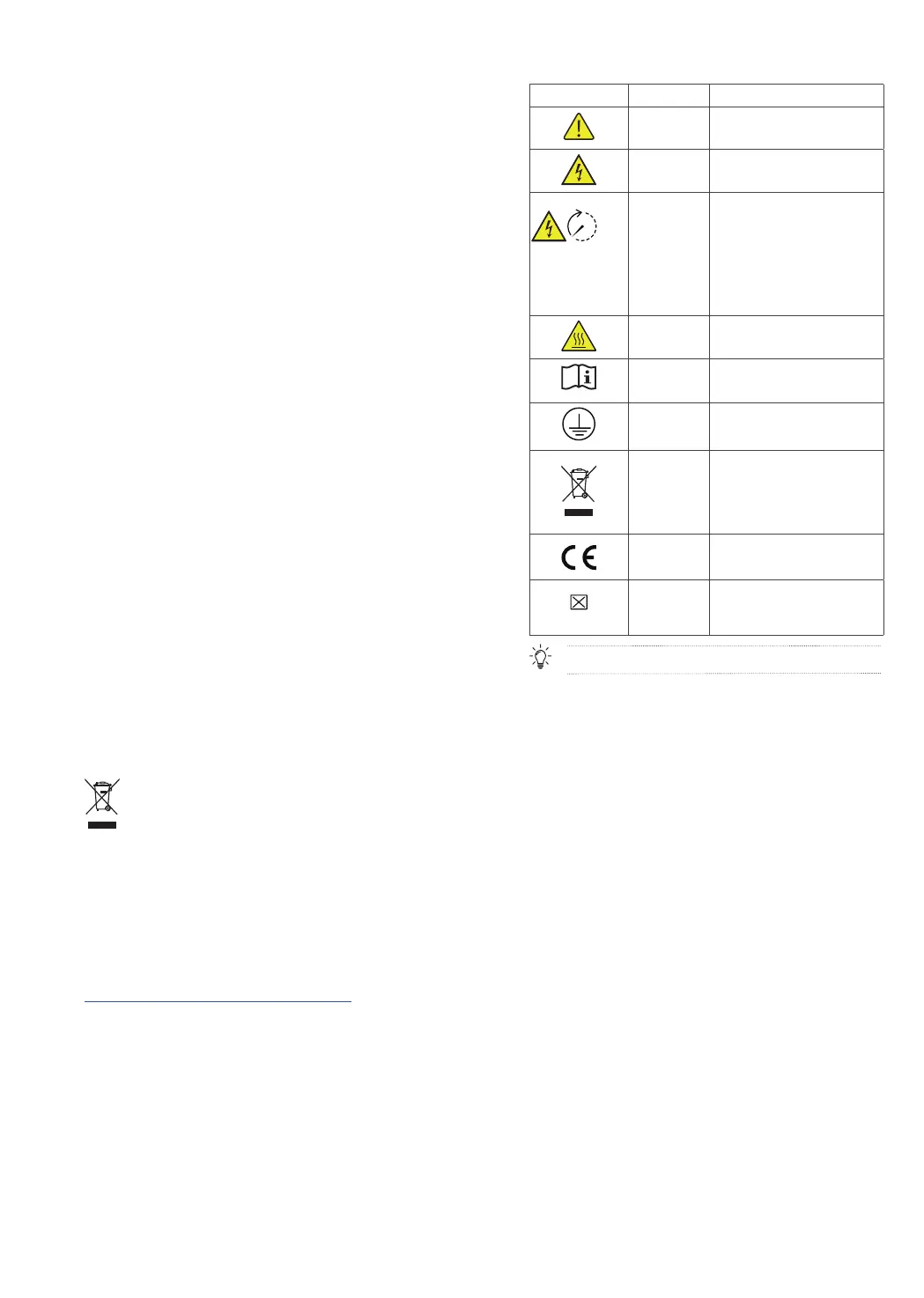
ENCLOSURE LABEL DESCRIPTION
Icon Name Meaning
Caution Caution, risk of danger
.
Eletric shock
warning
Caution, risk of eletric shock.
5 mins
Delayed
discharge
Danger to life due to high voltages
in the inverter; observe a waiting
time of 5 minutes.
High voltages that can cause lethal
electric shocks are present in the
live components of the inverter.
Prior to performing any work on
the inverter, disconnect it from all
voltage sources as described in this
document.
Burn warning
Do not touch a running equipment
because the enclosure is hot when
the equipment is running.
Refer to
documentation
Reminds operators to refer to the
documents delivered with the
equipment.
Grounding
Indicates the position for
connecting the protective earthing
(PE) cable.
Symbol of a
crossed-out
trash can
WEEE designation
Do not dispose of the product
together with the household waste
but in accordance with the disposal
regulations for electronic waste
applicable at the installation site.
CE marking
The product complies with the
requirements of the applicable EU
directives.
COM port
marking
The box with “×” indicates that the
port supports a protocol, while the
empty box indicates the port does
not support the protocol.
The labels are for reference only.