|3
Overview
The EcoFlow PowerOcean Plus redefines solar power utilisation to an
extreme, especially for houses with big and complex roof structures. With
up to 40kW solar input, 29.9kW AC output and dynamic tariff support, the
system achieves maximum power independence and financial savings on
energy bills.
Full compatibility with all EcoFlow home energy Ecosystem products,
smart monitoring and control over your household appliances can be
achieved right now.
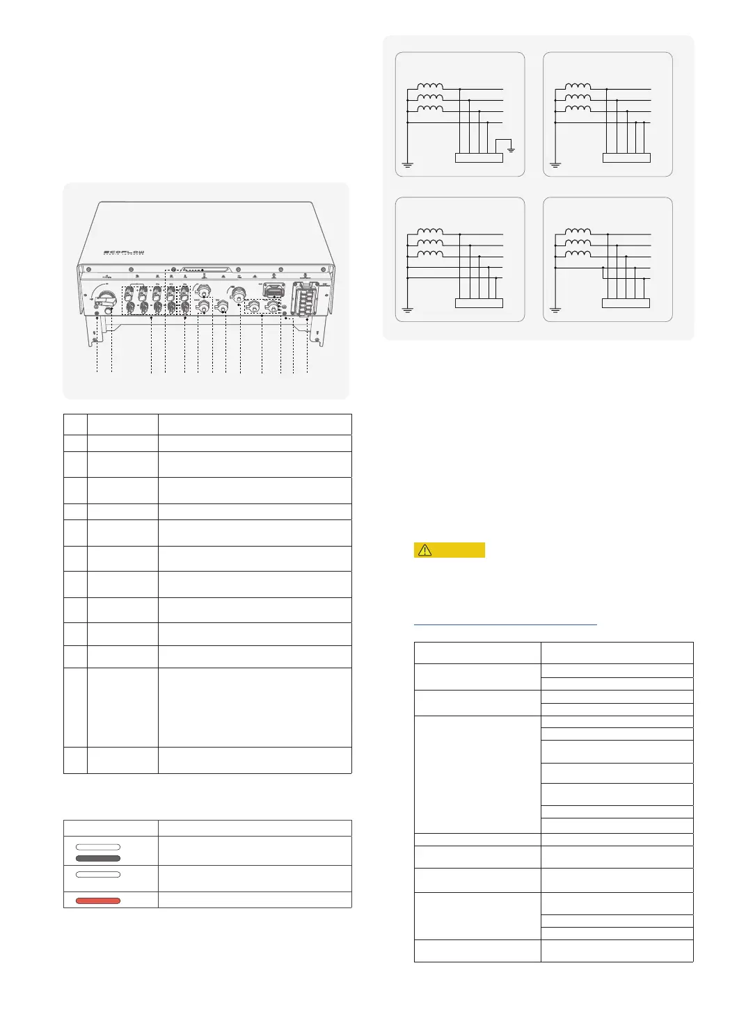
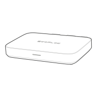
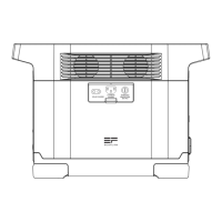
APPEARANCE
Key components and ports are shown below.
①
⑬
② ③
④
⑤
⑥ ⑦
⑧
⑨
⑩
⑪
⑫
No. Part Name Description
1 Earth stud Used for connecting ground wires.
2 PV switch
The control of PV inputs only, instead of
controlling any other voltage sources.
3 PV terminals
Used for solar panel connection. You can with up
to 4 ways of PV modules.
4 LED indicator See "LED indication" for details.
5 BAT terminals
Used for battery power connection. You can
connect up to 12 battery packs.
6 B-COM port
Used for communication between battery and
inverter.
7 4G port
Used for 4G wireless internet connection. Insert
EcoFlow 4G Dongle ESS (EU) if needed.
8 WAN port
Used for wired network connection and connecting
with the router in your home.
9 WIFI port Connects with EcoFlow WIFI Dongle ESS (EU).
10 PAR 1/2 port Used for inverter cascading communication.
11 COM terminal
Used for connecting with an emergency stop
(EPO), AC meters, ecosystem appliances, RCR or
DRM detector etc.
If you do not install an EPO, you must install the
supplied COM connector with shorting wire to the
COM terminal. Otherwise, the inverter will not
work properly.
12
GRID/BACKUP
terminal
Connects with the grid conductors and home
backup load conductors.
LED INDICATION
Status Description
on 1s
off 1s
Standby / Startup / Self-check / Over-the-air
updates / Alarm, system is still operating
Operating in grid-tied/backup mode
(post commissioning)
EPO shutdown / Fault, system cannot work
If the LED indicates a faulty status, visit the EcoFlow Pro app to retrieve the
error code for troubleshooting.
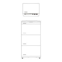
SUPPORTED POWER GRID TYPES
The inverter supports the following power grid types: TN-S, TN-C, TN-C-S,
and TT.
TT
N
L1
L2
L3
TN-C
PEN
L1
L2
L3
TN-S
N
L1
L2
L3
PE
TN-C-S
L1
L2
L3
N
PE
L1 L2 L3 N PE L1 L2 L3 N PE
L1 L2 L3 N PE
L1 L2 L3 N PE
WORKING PRINCIPLES
The inverter receives inputs from up to 4 PV strings. Then the inputs are
grouped into 3 MPPT routes inside the equipment to track the maximum
power point of the PV strings. 2 PV strings The DC power is then converted
into three-phase AC power through an inverter circuit. Surge protection is
supported on both the DC and AC sides.
This equipment applies to residential grid-tied systems. The system includes
PV strings, EcoFlow PowerOcean batteries, EcoFlow PowerOcean Plus
hybrid inverter, EcoFlow PowerOcean Plus Battery Junction Box & Base, AC
switches, and power distribution units.
System Installation
CAUTION
• Only qualified professionals are allowed to install, operate, and maintain
the equipment.
Refer to Installation Guide delivered with the equipment for installation
,
or
download the guide at
https://homebattery.ecoflow.com/eu/documentation
Installation procedure and the corresponding section is shown below
:
Step Section in the Installation Guide
Installation site survey
Installation Environment Requirements
Installation Space Requirements
Installation of LFP batteries and
the inverter
Installing Battery
Installing Inverter
Wiring
Connecting PE Cables
Connecting PV Input Cables
Connecting GRID/BACKUP Cables
Connecting Battery Power Cables
Connecting Battery Communication
Cables
Cascading Batteries
Connecting Smart Mater
Internet access Connecting to Internet
Installation completion
Installing trim cover on the battery
junction box and inverter
Installation review Checking before Power-On
Electrical energization and LED
indicator check
System Power-On
System Power-Off
LED Indicators
System commissioning via the
EcoFlow Pro app
System Commissioning