4
Wash Max
Figure 4-3
4.5 Determining the Reservoir Water Supply
The hot water supply for the VANGUARD Wash Max
Reservoir should fall within the range 120° F (48.9°C) to
150°F (65.5°C.). It must be a minimum of 12 psi (.844 kgm/
cm2) flow pressure with a minimum of 1 gallon per minute
(.063 liter/sec.) water flow.
1. Select the point for connection to the water supply so
that there is a minimum distance between the water
source and the reservoir. If this distance is less than 15'
(4.6 meters) and a minimum of 12 pounds (.844 kgm/
cm2) flow pressure is available, 1/4" O.D. copper tubing
is recommended,
refer to Figure 4-3.
If this distance is greater than 15' (4.6 meters) and/or
less than 12 pounds flow pressure (.844 kgm/cm2),
3/8" copper tubing is recommended for optimum perfor-
mance.
NOTE: DO NOT USE 180°F WATER SOURCE.
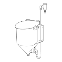
4.6 Plumbing into the Water Supply
1. Shut off water supply. Tap into the water source and
install the needle valve supplied with the reservoir,
refer
to Figure 4-3.
The needle valve provides a means to regulate water
flow to the dispenser and it permits servicing the sole-
noid valve without the need to shut off the main water
supply.
2. Install copper tubing between the needle valve and the
solenoid valve at bottom of detergent controller cabinet.
3. Install a length of copper tubing between the solenoid
valve and the vacuum breaker on the VANGUARD
Wash Max Reservoir.
4.7 Start-up Procedures
1. Adjust the VANGUARD EcoCenter, Control Max or
VANGUARD 2026 for proper detergent concentration.
Refer to the respective I/O Manual for instructions.
2. Fill the dishmachine with fresh water and turn on the
dishmachine with no detergent in the reservoir. The
controller will call for feed.
3. Check for water leaks and proper safety switch opera-
tion by lifting cover - the water flow should stop.
NOTE: Refer to Sections 4.8 - 4.11 only if you are using
the Guardian or Power Activator dispensers.
4.8 Guardian
Insure the GUARDIAN nameplate and safety label is neatly
and firmly attached to the front side of the reservoir. The
surface must be clean for permanent attachment. Attach the
GUARDIAN wall chart where it can easily be seen by the
dishmachine operators.
When the reservoir is used with a powdered GUARDIAN
detergent, the large fine mesh GUARDIAN screen must be
DETERGENT
CONTROLLER
SOLENOID VALVE
HOT WATER
SOURCE
NEEDLE
VALVE
TO WASH
TANK
Figure 4-4
inserted into the reservoir (before adding product). The
screen is installed with the small knob at the center top of the
screen facing up. The screen retainer ring is next inserted,
snug against the outer rim of the screen (with the prongs up).
This retainer ring is to hold the screen firmly in place,
refer
to Figure 4-4.
Up to 6 pounds (2.7 kg) of GUARDIAN detergent can now
be added to the GUARDIAN reservoir.
NOTE: Always wet a new screen before adding product
to avoid potential powder sift through.
Adjust the Senso-matic 26 for proper detergent concentra-
tion. Refer to Senso-Matic 26 I/O Manual (#6435) for details.
GUARDIAN
SCREEN
RETAINER
RING
POWER
ACTIVATOR
GRATE
 Loading...