5
4.9 Power Activator
Insure the Power Activator label is neatly and firmly attached
to the front side of the reservoir. The surface must be clean
for permanent attachment. Display the Power Activator wall
chart where it can easily be seen by the dishmachine
operators.
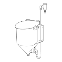
The Power Activator reservoir is for use with the solid
capsule detergents (i.e. SOLID POWER or EXCALIBER).
The small grate with the large mesh must be inserted into the
bottom of the reservoir. This grate is to keep any large
particles that may drop from the capsule and clog the tube,
refer to Figure 4-4
.
4.10 Electronic Overshoot Control Board
Adjustment
The following recommended timer settings are general and
"fine tuning" of the Overshoot Control Board must be done
at the account to deal with the specific conditions (i.e., water
temperature, pressure etc.) Follow procedures below:
Recommended Timer Settings
MACHINE ON OFF TOTAL PERCENT
TYPE TIME TIME TIME FEED
Door Type 2.5 sec. 7.5 sec. 10 sec. 25%
Conveyor/ 4 sec. 11 sec. 15 sec. 25%
Flight
Setting 9:00 11:30
On Timer -9:30 -12:30
4.11 Timer Setting Procedures
1. The left timer pot controls the "on" time and the right
timer pot controls the "off" time. The "on" time is when
the unit actually feeds detergent, and the "off" time is the
pause while dissolved detergent solution drains into
and disperses within the wash tank. The "on" timer is
always energized first and is identified by the red LED
light being illuminated. This light is not on during the "off"
time.
The "on" - "off" cycle repeats itself during the time the
Senso-Matic 26 is calling for feed.
2. Fill the dishmachine with fresh water and turn on the
dishmachine with no detergent in the reservoir. The
S-26 will call for feed. Adjust the timers.
3. Refer to the above chart for approximate time settings.
Adjust the left timer for "on" time and the right timer for
"off" time. These times can be easily measured by
observing the red LED light on the Overshoot Control
Board. As the S-26 is calling for feed, the red light will
pulse on and off. Time these and compare to the above
chart.
NOTE: Rotate timers clockwise to increase time
and counterclockwise to decrease time.
Figure 4-5
Figure 4-7
Figure 4-6
GUARDIAN
SENSO-MATIC 26
TO SAFETY SWITCH
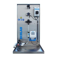
POWER ACTIVATOR
SENSO-MATIC 26 WITH OVERSHOOT CONTROL
EXCEPT CENTRON
POWER ACTIVATOR
SENSO-MATIC 26 OVERSHOOT CONTROL
IN CENTRON*
*CONNECT TO POWER ACTIVATOR PER CENTRON
MODEL 526 I/O MANUAL
 Loading...