Installation and Operating manual
Econ
®
Series 3300 Smart Valve Positioner www.eriks.com
Rev. 3 – January 22, 2019
12
3.2.1 Installation Steps
1. A correct bracket must be used in order to mount the positioner on the actuator yoke. Please
consider following important points when a custom bracket is being designed.
Ø Positioner’s feedback lever must be parallel to the ground at 50% of the valve stroke.
2. Feedback lever connection with the coupling of the actuator should be installed in such a way
that the valve stroke length coincides with the corresponding figure in “mm” marked on the
feedback lever. Improper setting may cause poor linearity and may create unnecessary hunting
during operation.
Assemble the positioner with the bracket supplied by fastening the bolts. Please refer to the
back of the positioner for size of the bolts. The standard bolt size is M8.
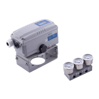
Figure 3301/3302
3. Check the valve stroke. The stroke marks are indicated on the feedback lever of the positioner.
Position the connection pin at the number on the feedback lever which corresponds to the
desired valve stroke. To adjust, move the bracket, the connection pin or both.
Correct way of Pin Insertion
4. Attach the bar slide assembly with the supplied mounting bolts onto the actuator coupling.
5. Mount the positioner with the bracket and the U-bolts onto the actuator yoke – DO NOT
 Loading...