Installation and Operating manual
Econ
®
Series 3300 Smart Valve Positioner www.eriks.com
Rev. 3 – January 22, 2019
19
4.5.3 Ground
1. Ground connection must be done before operating the positioner.
2. Open terminal cover and locate ground terminal plate on the right hand bottom side of the
terminal plate. The outer cable entry is located at outside of the terminal. Please make sure that
the resistance is less than 100 Ohm.
3. When using external ground, use (+) screw driver to unscrew the ground bolts. Insert outside
ground bolts and spring washer into ring type terminal of the ground cables and tighten them with
bolts.
4. When using internal ground, use 3mm wrench to loosen locking bolts of the terminal box cover.
5 Adjustments
5.1 Auto/Manual Switch (A/M Switch)
Auto/Manual Switch allows the positioner to be functioned as by-pass. If switch is set as Auto, the
positioner will operate per input signal. If switch is set as Manual, the positioner will send supply
pressure directly to the actuator.
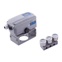
5.2 Variable Orifice Adjustment
Extremely small size of the actuator can
cause hunting of the positioner. To adjust
flow rate to the actuator, variable orifice can
be inserted. The size of orifice is Ø 1 mm.
Please note that these orifices can only be
used in conjunction with a gauge block. The
orifices are supplied standard with the
optional gauge block.
 Loading...