7
INSTRUCTION MANUAL ECOSOFT
®
MEDIA SYSTEMS
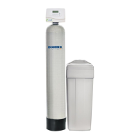
2.2. FK, FU Cabinet
If your cabinet was delivered with pre-loaded media, place the cabinet in the installation spot, ll salt
compartment with salt, then perform step 6 of simplex installation procedure above.
1. Disconnect ⅜″ exible tube from brine elbow of control valve. Unmount the valve by screwing
counterclockwise. Remove the valve, then remove quick connector piece if present.
2. Plug or cap top end of the riser pipe to avoid letting media particles inside. Use funnel to carefully pour
the media in the tank. When loading the tank, maintain vertical orientation of riser pipe. If the pipe tilts,
restore it to straight vertical direction. When nished, rinse thread of tank opening with water and remove
any media particles stuck in thread groove. Install connector piece if necessary and screw control valve
back on FRP tank.
3. Place the cabinet in the installation spot. Install ¾″ pipe in control valve drain tting and run it to oor
drain or pipe socket. Fix the drain pipe end above oor drain to provide at least 1″ wide air gap. Open lid
and ll salt compartment with softener salt at least half full.
4. Install connection tting kit: mate the tting to control valve ports and screw the coupling nuts on port
threads. Do not put any mechanical load on ttings or use them to support pipes.
Connect the system to water supply and downstream pipework without opening water supply shut-
o valves. Observe correct ow direction when connecting pipes. Inuent and treated water ports are
indicated with arrows on control valve.
Start manual regeneration of the system. Scroll regeneration to backwash if it is not performed on 1st
cycle of regeneration sequence. As soon as the control valve starts backwashing, slightly open entry
shut-o valve to let water in the system. Air will escape via drain line with an audible hiss. When water
emerges from the drain line, open the entry valve completely. Carefully inspect the system for leaks.
Let the system nish regeneration, then start one more
2.3. FK, FU Twin
Twin systems are equipped with WS1CE Twin specially designed control valve. The valve has two special
side ports for connecting to twin tank. Twin operation allows for uninterrupted treated water supply without
the need to use raw water when the system is regenerating.
1. Install FRP tank on rm level surface capable of supporting its weight. Put riser pipe in the tank bottom
distributor rst. Ensure that top end of riser pipe is level with the top opening of FRP tank (within +5 mm).
2. Plug or cap top end of the riser pipe to avoid letting media particles inside. Use funnel to pour the media
in the tank. When loading the tank, maintain vertical orientation of riser pipe. If the pipe tilts, restore it to
straight vertical direction. When nished, rinse thread of tank opening with water and remove any media
particles stuck in thread groove. Repeat with the second tank
3. Lock top distributor in circular slot at the bottom of control valve shank. Install control valve on the lead
tank. Mate the distributor with top end of riser pipe, then screw control valve on tank. Turn the tank so
that the control valve’s side ports face the other tank. Attach second top distributor to in-out head and
screw it on the second tank. Use interconnectors pack to join in-out head with control valve. Fix the
coupling nuts rmly.
4. Install ¾″ pipe in control valve drain tting and run it to oor drain or pipe socket. Fix the drain pipe end
above oor drain to provide at least 1″ wide air gap.
5. Place the brine tank next to FRP tank. Install ⅜″ exible tube in brine elbow and run it to brine tank.
Remove tank lid and brine well cap, pull the tube inside the well and connect it to brine valve, then
re-assemble in reverse order. Fill the brine tank with salt at least half full
6. Install connection tting kit: mate the tting to control valve ports and screw the coupling nuts on port
threads. Do not put any mechanical load on ttings or use them to support pipes.
Connect the system to water supply and downstream pipework without opening water supply shut-
o valves. Observe correct ow direction when connecting pipes. Inuent and treated water ports are
indicated with arrows on control valve.
Start manual regeneration of the system. Scroll regeneration to backwash if it is not performed on 1st
cycle of regeneration sequence. As soon as the control valve starts backwashing, slightly open entry
shut-o valve to let water in the system. Air will escape via drain line with an audible hiss. When water
emerges from the drain line, open the entry valve completely. Carefully inspect the system for leaks.
Let the system nish regeneration, then perform one more manual regeneration.
 Loading...